Vermes
Advanced Member level 4

- Joined
- Aug 2, 2011
- Messages
- 1,163
- Helped
- 0
- Reputation
- 0
- Reaction score
- 0
- Trophy points
- 1,316
- Activity points
- 22,318
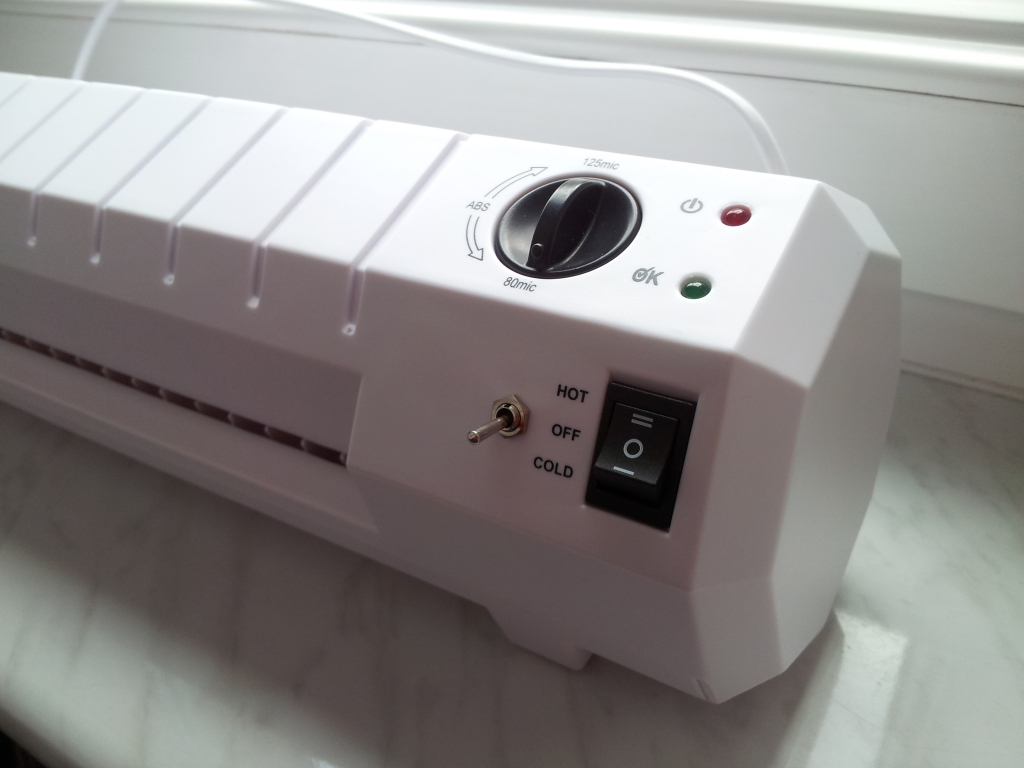
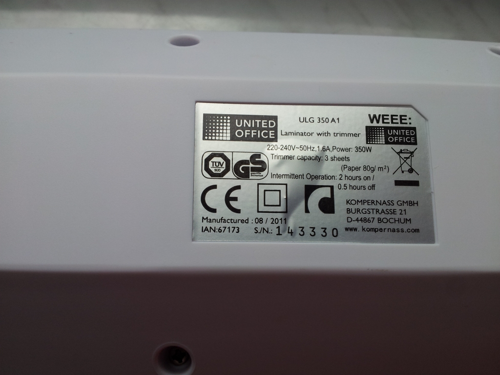
It is a construction of home made laminator for PCB and foil (as it was originally designed to be). Picture below shows the parameters of fabric device.
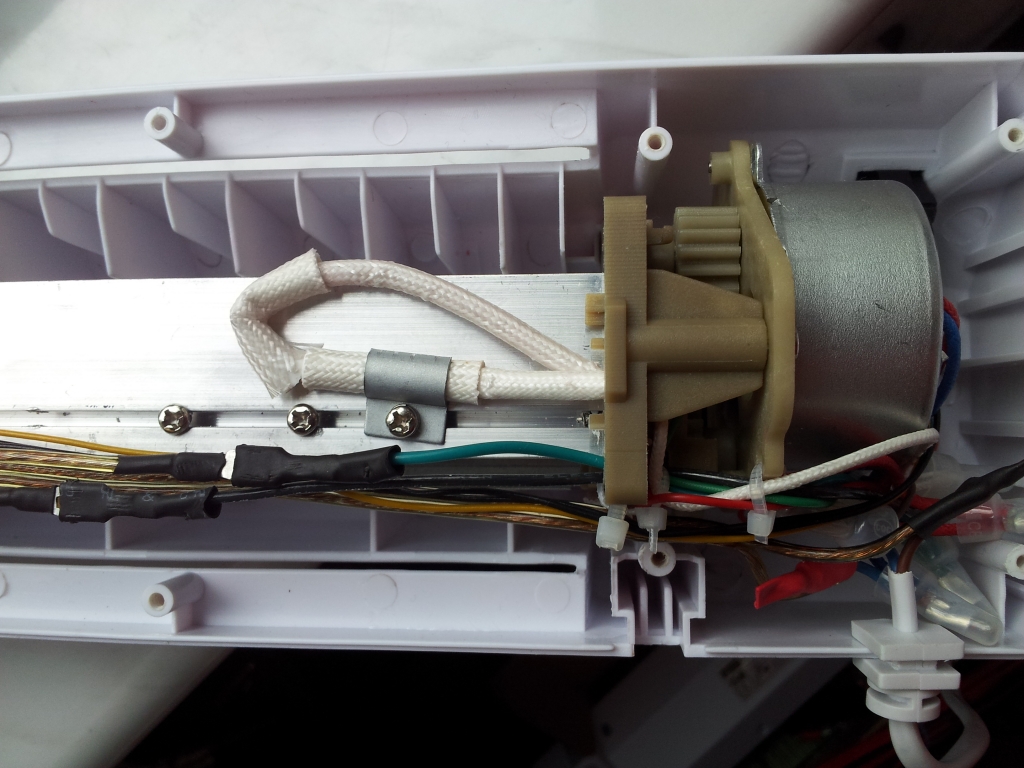
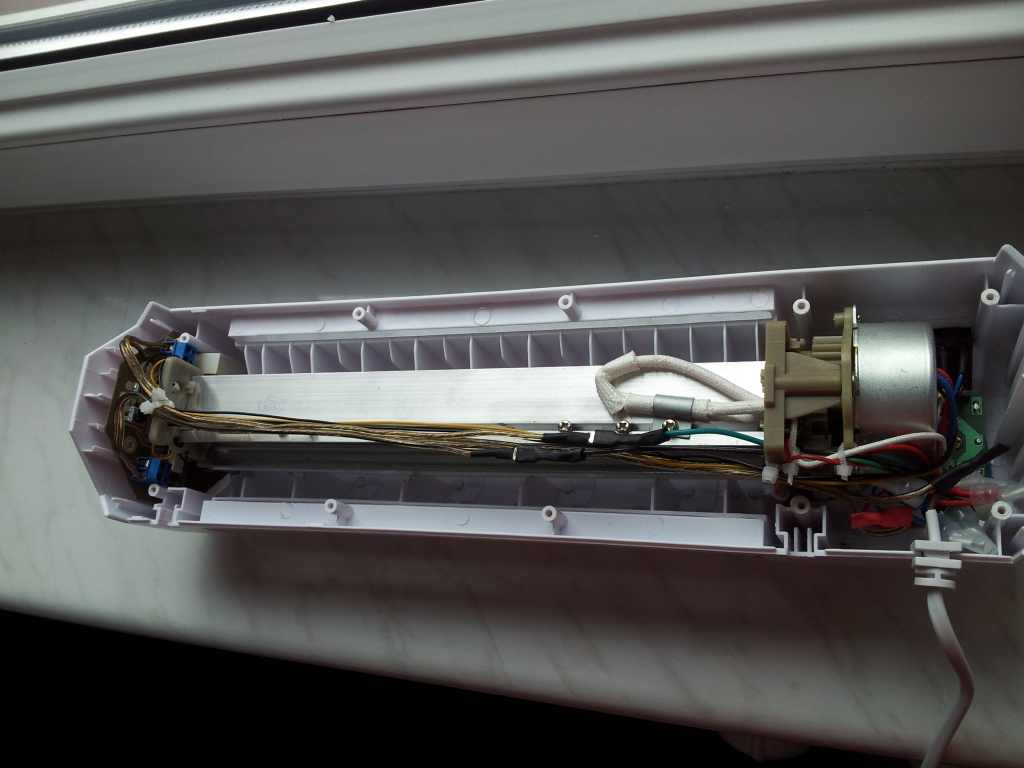
It was modified to gain an additional function of making PCB instead of thermal transfer. After disassembly of the original laminator, you have to remove two bimetallic thermostat which were connected in series – one for 120 degrees and the second for 145 degrees. It is good not to remove the thermal fuse because it provides the thermal protection.
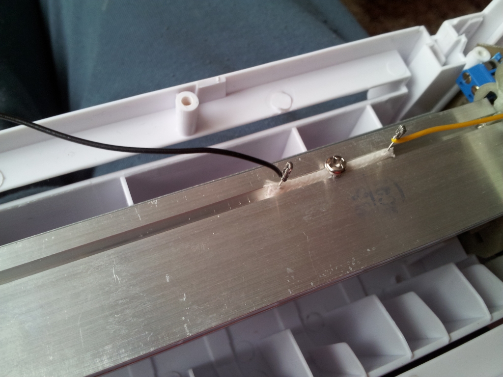
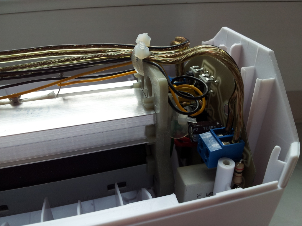
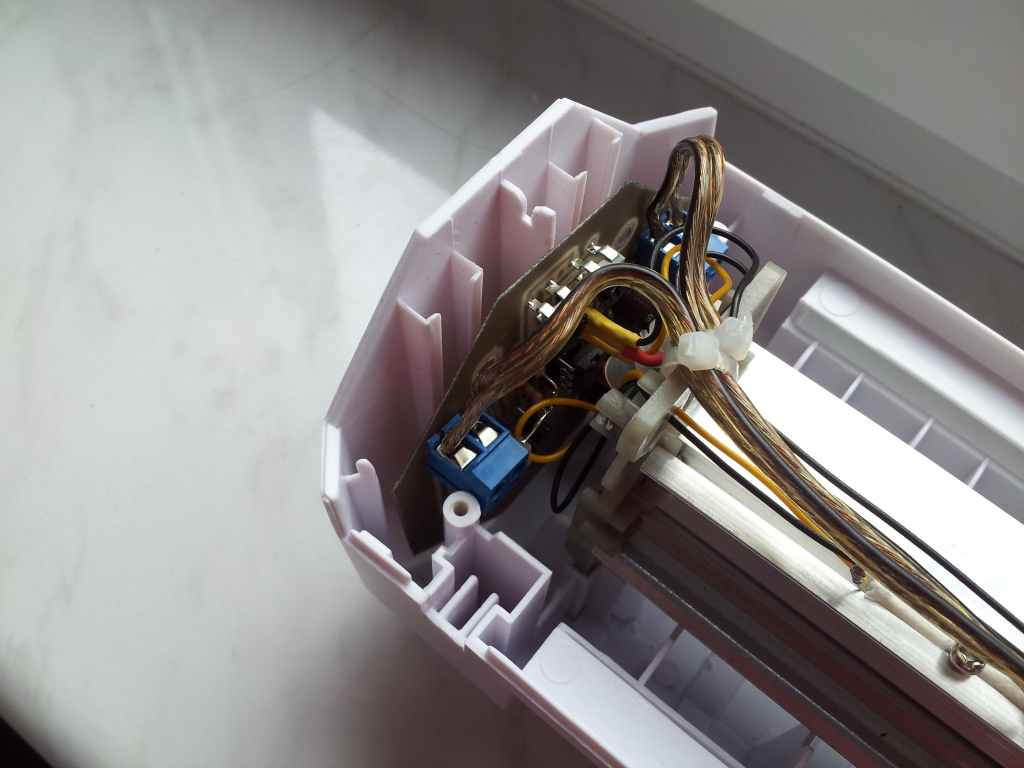
Picture below presents the sensor attached:
Schematic:
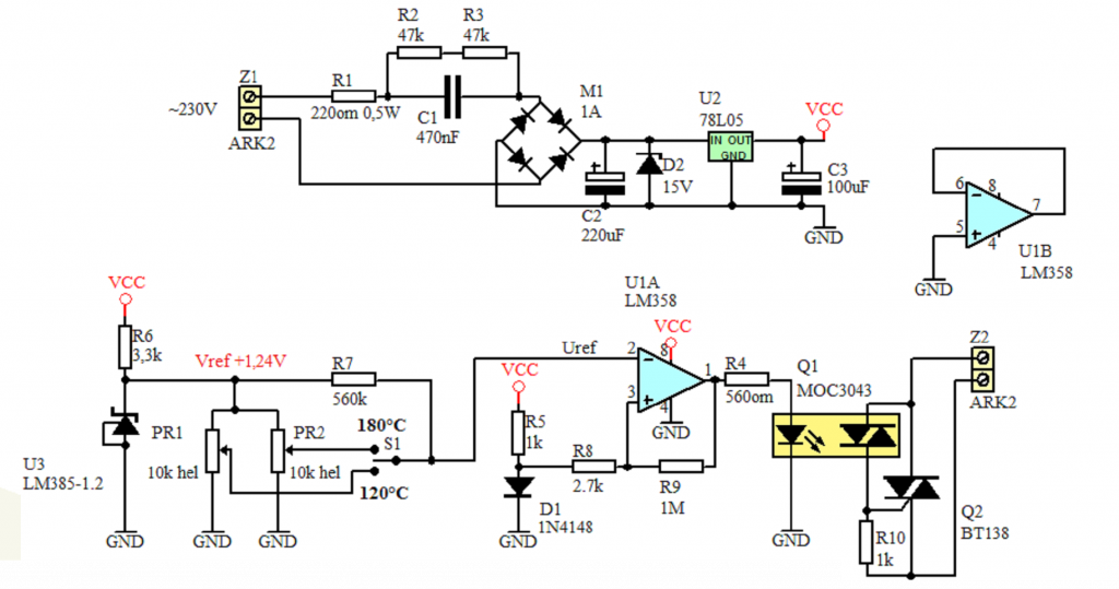
The sensor in this design is diode 1N4148 inserted in a piece of material resistive to the high temperature and screwed to the heater.
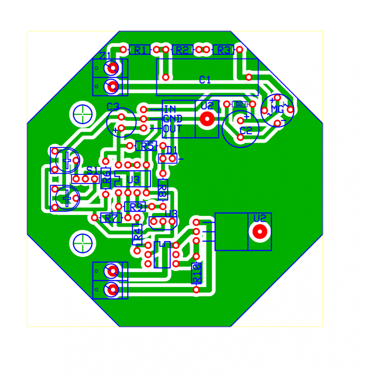
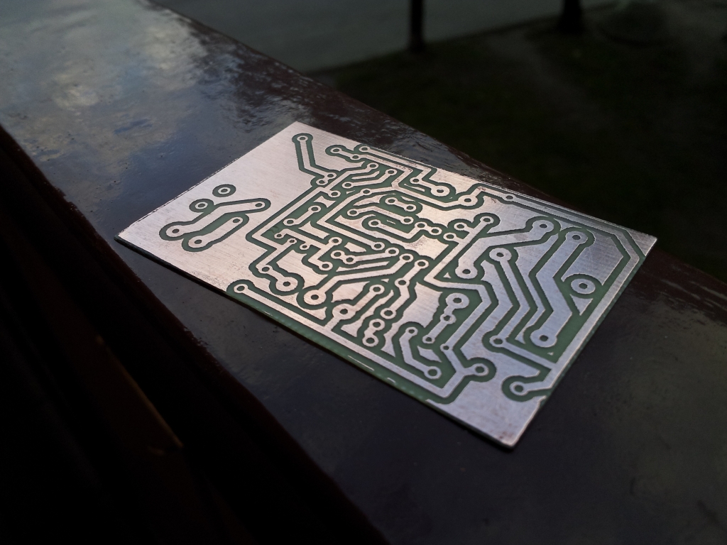
PCB was made in Express PCB:
In addition, a switch was added to the original device, that switches between the temperatures 120 degrees Celsius for the foil and 180 degrees Celsius for the PCB. When you want to cool the laminator, just turn it off.
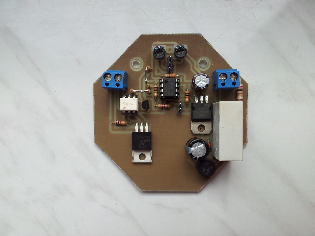
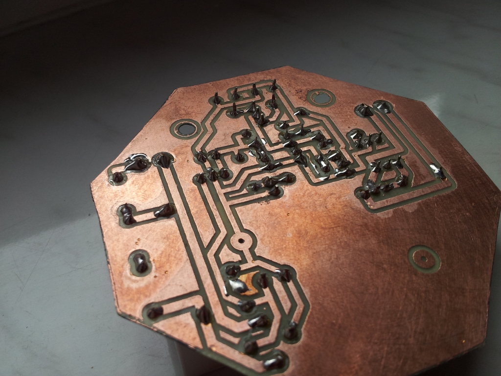
Pictures:
Link to original thread (useful attachment) - Laminator, Laminarka PCB