Vermes
Advanced Member level 4
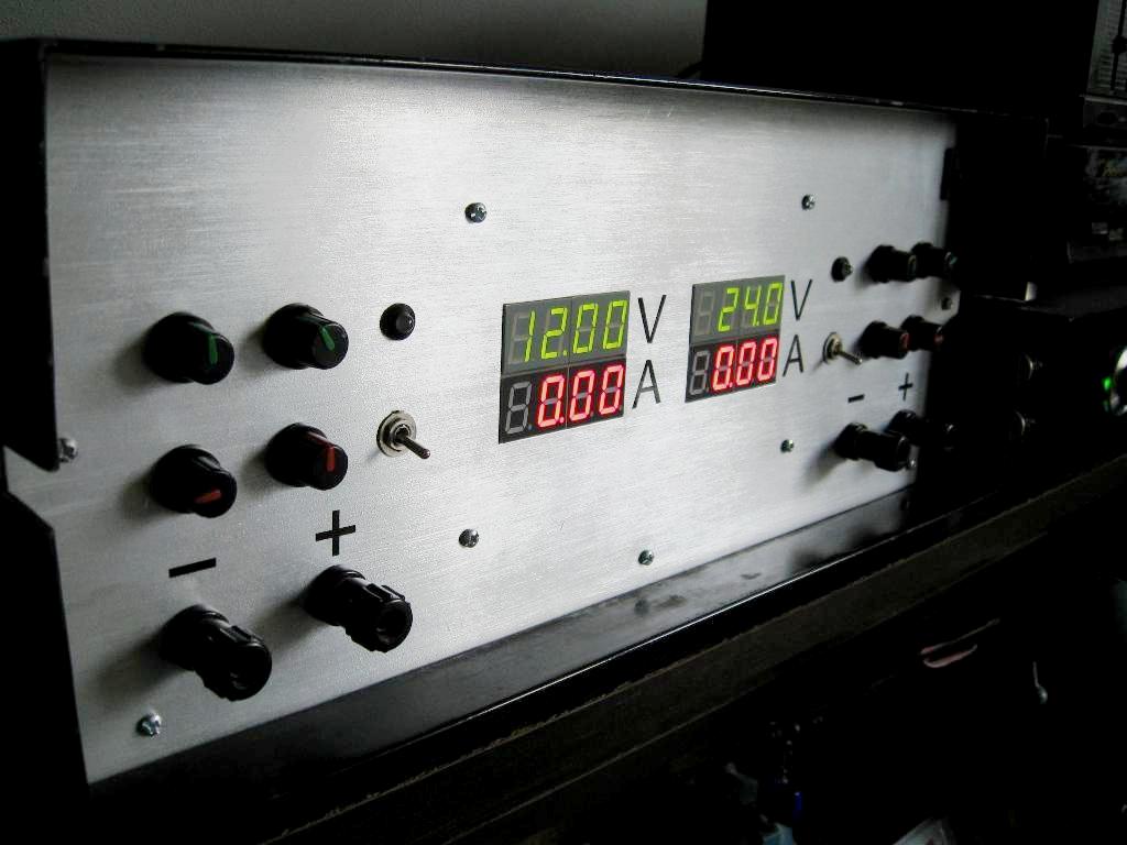
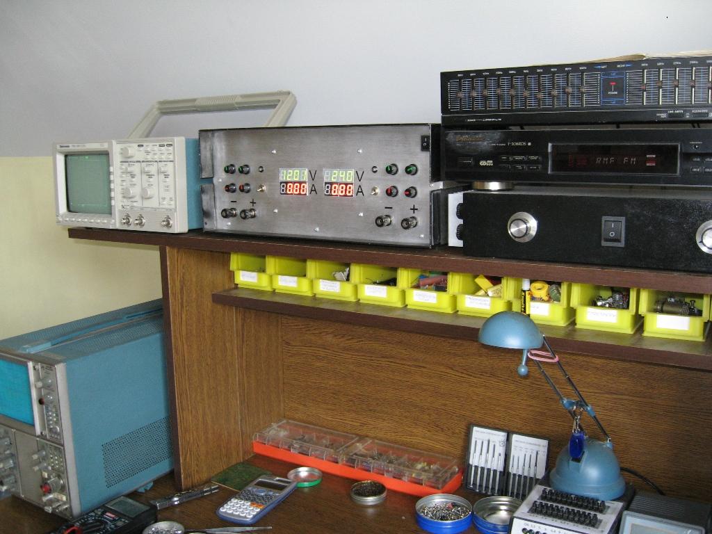
It is a laboratory power supply 2x30V, 2x6A.
Construction:
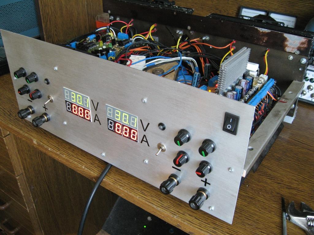
The housing was made of a housing from the power supply Unitry. The whole was cleaned with sandpaper. The front panel was cut from aluminum plate 1,5mm thick. From the top side, it was finished with a grinder and thick sandpaper, which made the surface matt. Holes for the displays were drilled with a drill 3mm, and then polished with files.
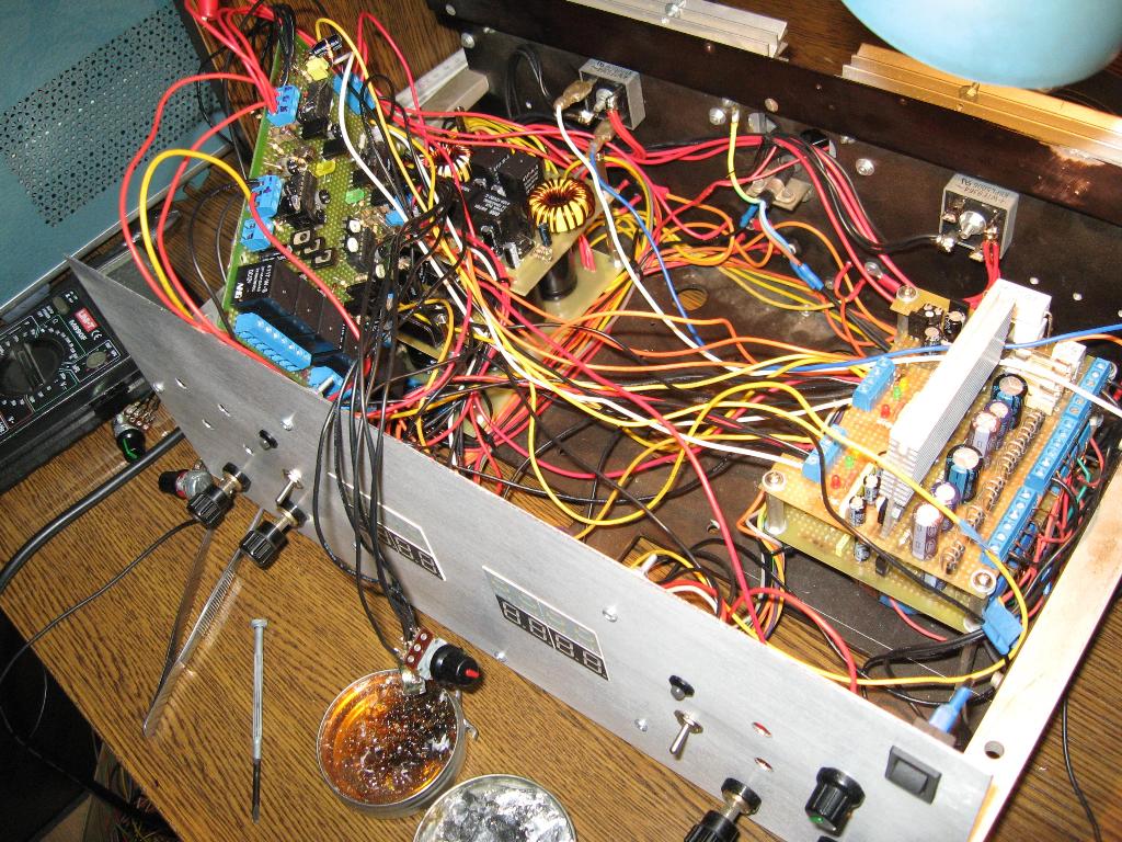
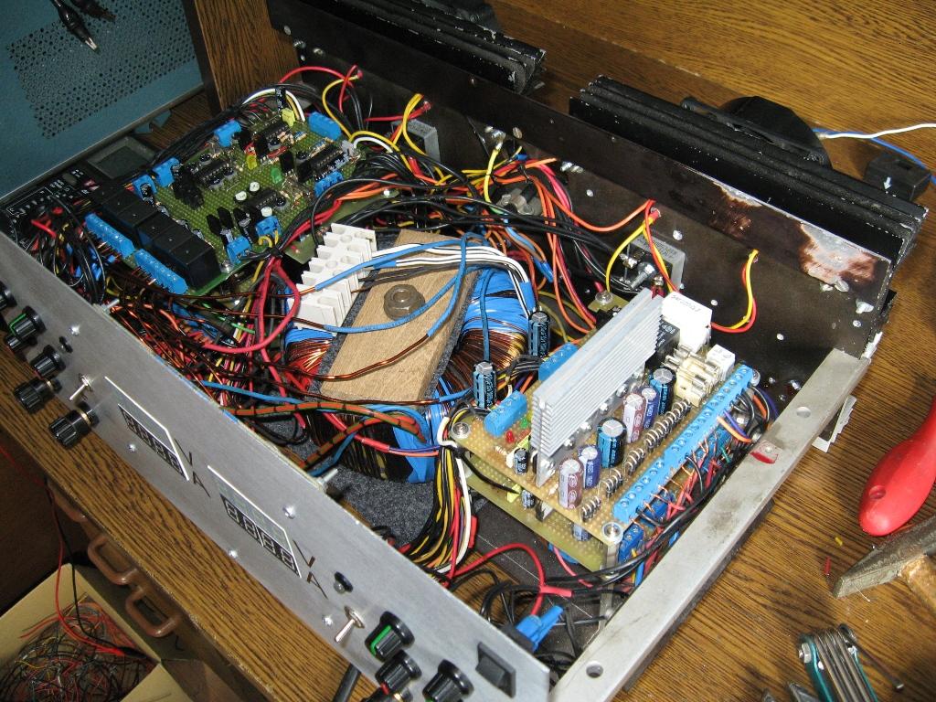
The main transformer is toroid 400W. It has 8 windings (about 9V each). Windings switch automatically depending on the output voltage at 8V, 16V and 24V (4 windings per channel) to reduce the “radiator effect”.
Auxiliary transformer is a toroid 60W. It has a 4x symmetrical output 5V for voltage and current indicators and 2x3,3V, 2x12V, 2x21V power the control system, automatic winding switching, soft-start systems, short circuit protective systems and fan control. All voltages were stabilized and filtered.
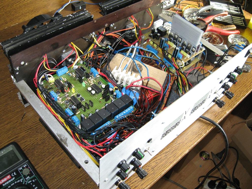
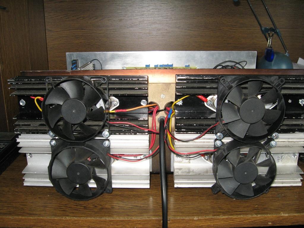
Each channel has a rectifier bridge 25A and filtration of 15000mF (5x3300uF per side). Thus the power supply is very rigid and without ripples at maximum load. Everything was mounted from the bottom, one on the other board using hexagonal spacers. At the bottom of the left side there are leveling resistors and shunts screwed to the plate, the above filtration and fan controller, the above control, the auxiliary power in a compact module on the left side. Implementing transistors are 2N3055 (4 pieces per channel) on the radiators, on the back of the housing. The entire current path from the transformer to the output terminals is run by 3mm² thick cables.
Principle of operation:
Operation of the power supply is a classic one. Differential systems are on operational amplifiers. The output voltage sets the voltage divider on the reference diode. Operational amplifier compares the reference voltage with the output and by the negative feedback, stabilizes it to a preset value. It monitors the voltages at the terminals, so the voltage drops on the wires inside the power supply are well compensated. Another operational amplifier performs the function of a current stabilizer (limitation), also for a preset value, which can not be exceeded (even for short circuit), adjusting the voltage in the function of current. The next two are used to disable the channel voltage for short circuit or overload. In total, there are 20 operational amplifiers in the power supply. Winding switching systems operate independently. The windings switch automatically at voltages 8, 16 and 24V. Relays 20A NHG were used for this purpose. Also the voltmeters operating ranges switch automatically.
Voltmeters and ammeters are based on systems ICL7107, schema was taken from the directory note. Measurement of voltage at the terminals. Current measurement from the shunts consisted of resistors 0,05ohm/10W. Each indicator must have a separate symmetric power and stabilizers, which has an impact to a number of windings of the auxiliary transformer. Current limit can be fixed, or immediately after exceeding – disconnect the output voltage. The switch on the front panel is used for this, and the diode above the switch indicates the present state. When the power supply is operating in the state of current source (active current stabilization), the diode lights red, when the voltage”pops out”, the diodes color turns green. Potentiometers are used to rough and precise current and voltage adjustment in two channels independently.
Protection:
Each block is preceded by fuses with values close to the maximum current flowing. The main transformer is started by the soft-start on the transistor with a capacitor and resistor, which causes arcing the relay contacts. Also both power supply channels are equipped with soft-start. After turned on, the automatics switch on the main transformer after 3s (previously it runs through the resistor 100ohm/10W and gently charges the filtering capacitors) and channels after 4s. Soft-starts are made on the operational amplifiers, thanks to what, the inclusion moment is certain and precise. Cooling the implementing transistors is with reserves (heat sinks areas), but even so additional active cooling turns on automatically when the temperature exceeds 45 degrees Celsius. Sensor is a transistor working in the OC system, where the output voltage (in a small range) varies depending on temperature. The operational amplifier monitors the voltage. High state appears at its output after exceeding the set temperature. After cooling down the system, fans stop themselves.
Link to original thread (useful attachment) – Zasilacz laboratoryjny 2x30V, 2x6A inny niż wszystkie.