kapurk
Newbie level 5
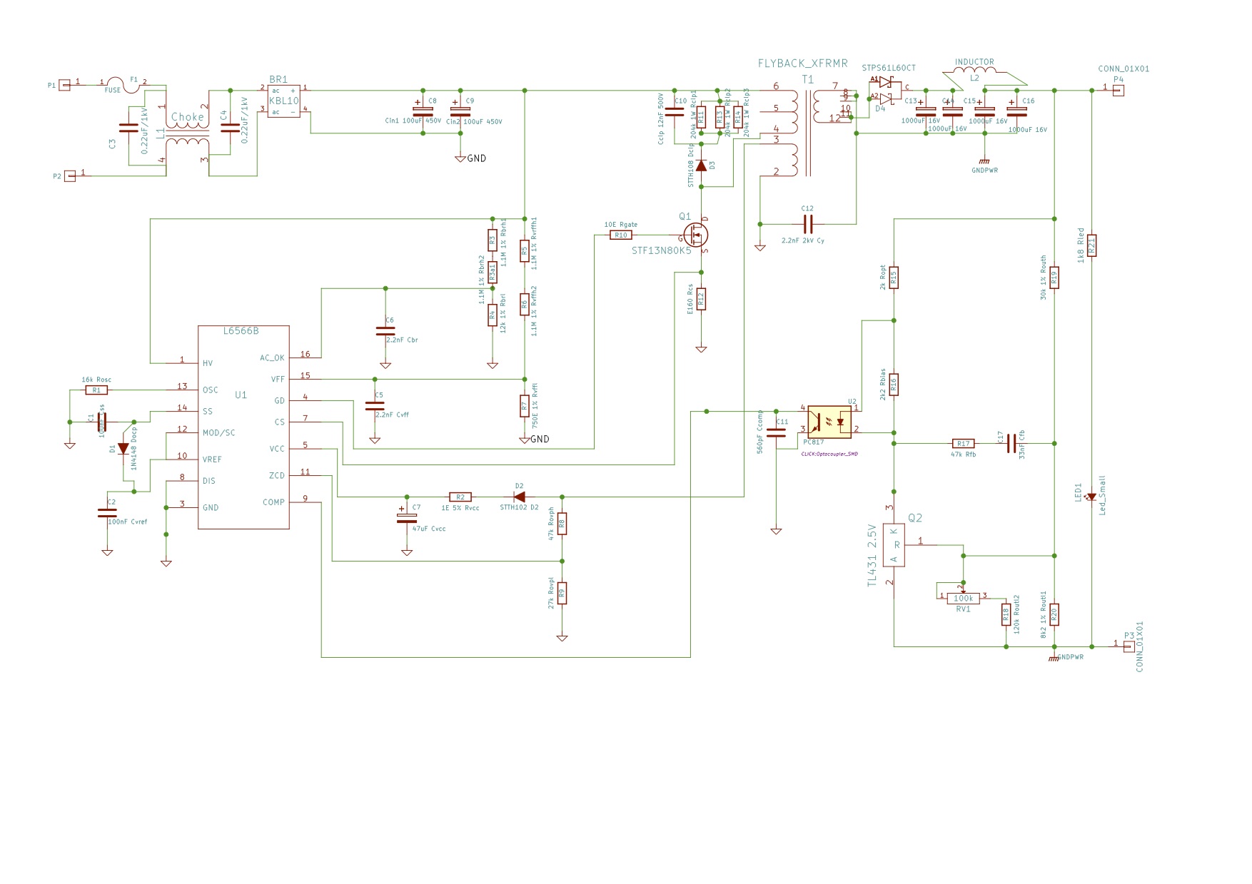
I am trying to get a prototype SMPS board for a 12V 10A output using the L6566B to work. The circuit design has been done using the edesignsuite on the ST website. I have got a few boards made professionally for prototyping after designing them with KiCAD. I have a fair bit of experience with power supplies using the 3842 PWM controller but getting this L6566B board to work is proving to be a challenge.The controller takes its own time starting up. In fact it starts up quickly if I touch some points on the pcb with a multimeter probe. But then after startup it seems to shutdown or remain in burst mode the moment I put some load on it (less than 1A). I have tried disabling some of the protection features by tying Vff (pin 15) to ground and AC_OK to Vcc as suggested by the datasheet.
The circuit is designed for QR mode operation. For test purposes I am using a 0R33 resistor for Rcs and 15k for Rosc. The transformer is a PQ3220 that is taken from a 3842 based SMPS. Would the L6566B shutdown with minor variations in turns ratio? I have tried changing the ratio of Rovp_h and Rovp_l but to no avail.
The opto is K817C with a TL431 voltage ref.
Vcc measurements show a cyclic variation between approx. 8V and 13V. Vref is 5.06 - 5.07V. What is confusing is that the Pin 13 shows only about 0.2V whereas the datasheet says it is an accurate 1V source. The scope shows no waveforms or pulses when on load but it does show an occasional single pulse at the MOSFET drain on no load. This pulse is sufficient to charge the output capacitors to light up an LED which slowly goes dim and then brightens up when the next pulse comes.
Any tips on what could be going wrong?