Welcome to our site! EDAboard.com is an international Electronics Discussion Forum focused on EDA software, circuits, schematics, books, theory, papers, asic, pld, 8051, DSP, Network, RF, Analog Design, PCB, Service Manuals... and a whole lot more! To participate you need to register. Registration is free. Click here to register now.
Google "555 astable multivibrator" and look at a few of the websites you get back. There are MANY that talk about how the circuit works... all the way down to the nitty-gritty details about the level comparisons and current mirrors inside the 555 IC.
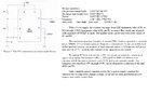
555 timer is a clock provider, in fact n oscillator. it generates a constant square wave, its frequency and time period can b set through the attached RC circuit. the valus of R, C can b set through farmulae including duty cycle.
In its design its is an 8 Pin IC
you can have a useful view of
This site uses cookies to help personalise content, tailor your experience and to keep you logged in if you register.
By continuing to use this site, you are consenting to our use of cookies.
")