Continue to Site

Welcome to EDAboard.com

Welcome to our site! EDAboard.com is an international Electronics Discussion Forum focused on EDA software, circuits, schematics, books, theory, papers, asic, pld, 8051, DSP, Network, RF, Analog Design, PCB, Service Manuals... and a whole lot more! To participate you need to register. Registration is free. Click here to register now.

key debouncing elimination with hardware

Status
Not open for further replies.

chintesh

Newbie level 1
Joined
Oct 7, 2011
Messages
1
Helped
0
Reputation
0
Reaction score
0
Trophy points
1,281
Activity points
1,292
hey guys i have read about the key debouncing concept and methods to remove it with the help of software by increasing the delay but if i want to remove it with the help of capacitors then what values of capacitors and resistors should i use?
 

you can calculate yourself using RC equation

example
For 5msec delay,
If Vdc=10, R=100E then C= 10uF
 

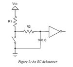
debouncerrc.jpg

Hi all, regarding the RC debouncer (attached), in choosing the value of R2 for this, the author of this Debouncing Part 2 page originally chose 180K for this, but when he considers there's leakage current from the 74AHCT14 hex inverter of 1uA from the input, he up the cap value and changes R2 to 18k instead. I don't understand the mechanic for this, does it mean that the hex inverter is actually sourcing 1uA which goes through the R2 resistor to ground?
 

That is what Ganssle is saying.

Source: Ganssle, part 2, just before the diode circuit.
But. the analysis ignores the gate's input leakage current. A CMOS device like the 74AHCT14 dribbles about a microamp from the inputs. That 180K resistor will bias the input up to .18 volts, uncomfortably close to the gate's best-case switching point of 0.5 volt. Change C to 1 µF and R2 is now 18K.

I don't understand your question apart from that.

John
 

So, when it says "74AHCT14 dribbles about a microamp from the inputs", does that mean the 74AHCT14 is demanding the current (sink) or giving out the current (source)?
 

Here is a section form the datasheet directly:
25_1318025169.png


The three columns represent minimum, maximum, and maximum at 125°C. I interpret that the positive current is sourcing.

John
 
  • Like
Reactions: qdnboy

    qdnboy

    Points: 2
    Helpful Answer Positive Rating
Status
Not open for further replies.

Part and Inventory Search

Welcome to EDABoard.com

Sponsor

Back
Top