Continue to Site

Welcome to EDAboard.com

Welcome to our site! EDAboard.com is an international Electronics Discussion Forum focused on EDA software, circuits, schematics, books, theory, papers, asic, pld, 8051, DSP, Network, RF, Analog Design, PCB, Service Manuals... and a whole lot more! To participate you need to register. Registration is free. Click here to register now.

[SOLVED] JHD162A LCD Bricked!

Status
Not open for further replies.

anishd19

Newbie level 5
Joined
Jan 1, 2012
Messages
10
Helped
0
Reputation
0
Reaction score
0
Trophy points
1,281
Activity points
1,394
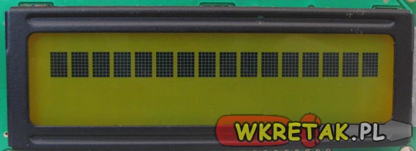
I, by mistake, forgot to remove LCD from microcontroller (ATmega8A) while programming. The LCD is totally bricked. Is there a way to recover my LCD?

I tried google and even searched our forum. Please help me ASAP, I need it for my review of final year project tomorrow. Brand new it is!! :/
 

Are you using standard ISP/SPI programming or high voltage programming (HVP)?

Typically, ISP/SPI programming will not damage an LCD/GLCD.

Can you post a schematic of your design?

Have you attempted to program to AVR with know working firmware, to verify the JHD162A is indeed damaged.

Double check the connections and any solder joints.

If it is damaged and ISP/SPI programming was used, then most likely it was damaged by static discharge, etc.

Unfortunately, if it was damaged by HVP, most likely it's toast.


BigDog
 

check with any other program if your LCD is working ? Normally you dont need to remove LCD while programming processor !
 

I use usbasp SPI to program my controller.

ATmega8.JPG


D0 - D7 of lcd --> PB0 - PB7 of m8
RS ---> PD2 (INT0)
RW ---> PD1 (TXD)
E ---> PD0 (RXD)


PB3, PB4, PB5 happen to be the MOSI, MISO, SCK.

Sorry I don't have a digital schematic! hope the above info is equivalent.


Yes, I did try Reprogramming with the known working programs. yet it showed no results, just dark pixels ( tried adjusting the contrast pot).

Are you using standard ISP/SPI programming or high voltage programming (HVP)?

Typically, ISP/SPI programming will not damage an LCD/GLCD.

Can you post a schematic of your design?

Have you attempted to program to AVR with know working firmware, to verify the JHD162A is indeed damaged.

Double check the connections and any solder joints.

If it is damaged and ISP/SPI programming was used, then most likely it was damaged by static discharge, etc.

Unfortunately, if it was damaged by HVP, most likely it's toast.


BigDog
 

After examining your connections, I see no indication that the LCD was damaged via ISP/SPI programming.


Does your LCD resemble the following:


If so, such a display typically indicates improper initialization.

Post your known test code.


BigDog
 

Yes, I did try Reprogramming with the known working programs. yet it showed no results, just dark pixels ( tried adjusting the contrast pot).

I've been thinking that the SPI programming will interfere with the LCD driver if the pins are common. I also had the power to LCD connected.

Could the reason be this line of my code?

Code:
Send_A_Command(0x80 + 0xc9); //go to location 0xc9//
foolish it is! but I didn't realize till programming! 0x80 + 0xc9 = 0x149 = ob 1 0100 1001 . what does it mean? could it

have bricked my LCD.

where Send_A_Command is coded as:

Code:
void Send_A_Command(unsigned char command)
{
	CheckLCDBusy();
	LCDDataPort = command;
	LCDControlPort &= ~(1<<LCDReadWrite | 1<<LCDRegisterSelect);
	LCDEnable();
	LCDDataPort = 0;
}

I was trying desperately to find the hexadecimal addresses of my LCD DDRAM. (from a youtube source)


check with any other program if your LCD is working ? Normally you dont need to remove LCD while programming processor !

- - - Updated - - -

Yes!.. It looks just like the picture.

here is my entire code..

main.c

Code C - [expand]
1
2
3
4
5
6
7
8
9
10
11
12
13
14
15
16
17
18
19
20
21
22
23
24
25
26
27
28
29
30
31
32
33
34
35
36
37
38
39
40
41
42
43
44
45
46
47
48
49
50
51
52
53
54
55
56
57
58
59
60
61
62
63
64
65
66
67
68
69
70
71
72
73
74
75
76
77
78
79
80
81
82
83
84
85
86
87
88
89
90
91
92
93
94
95
96
97
98
99
#include <avr/io.h>
#include <util/delay.h>
#include <stdlib.h>
 
#define LCDDataPort     PORTB
#define LCDDataPortDir      DDRB
#define LCDControlPort      PORTD   //always output
#define LCDControlPortDir   DDRD
 
#define LCDEnablePin        0   
#define LCDReadWrite        1
#define LCDRegisterSelect   2
 
void CheckLCDBusy(void);
void LCDEnable(void);
void Send_A_Command(unsigned char command);
void Send_A_Character(unsigned char character); 
void Send_A_String(char *StringOfCharacters);   
 
int main(void)
{
    LCDControlPortDir |= 1<<LCDEnablePin | 1<<LCDReadWrite | 1<<LCDRegisterSelect;
    _delay_ms(15); 
    
    Send_A_Command(0x01);   //Clear Screen
    _delay_ms(2);
    Send_A_Command(0x38);   //8 bit mode
    _delay_us(50);
    Send_A_Command(0b00001110); //control cursor, display on/off
    _delay_us(50);
    
 
    char positionString[4]; //can also do it as a pointer *char...
    
    while(1)
    {
        for(int x;x<128;x++)
        {
            Send_A_Command(0x80 + x);      //set the current location
            Send_A_String("x");                   //put an x at that location
            itoa(x, positionString, 10);
            Send_A_Command(0x80 + 0xc9);//display the location as a number at bottom right (C9)
            Send_A_String(positionString);
            _delay_ms(50);                        //add a delay to slow it down
            Send_A_Command(0x80 + x);     //go back to the location
            Send_A_String(" ");                  //put a space
        }
    }
    
}
 
void CheckLCDBusy()
{
    LCDDataPortDir = 0; //input mode
    LCDControlPort |= 1<<LCDReadWrite;
    LCDControlPort &= ~1<<LCDRegisterSelect; //command mode
    
    while (LCDDataPort >= 0x80) //D7 on PORTB Pin7 will be 1 when busy else 0
    {
        LCDEnable();
    }
    
    LCDDataPortDir = 0xFF; //0b11111111
}
 
void LCDEnable()
{
    LCDControlPort |= 1<<LCDEnablePin;
    asm volatile ("nop");
    asm volatile ("nop");
    LCDControlPort &= ~1<<LCDEnablePin;
}
 
void Send_A_Command(unsigned char command)
{
    CheckLCDBusy();
    LCDDataPort = command;
    LCDControlPort &= ~(1<<LCDReadWrite | 1<<LCDRegisterSelect);
    LCDEnable();
    LCDDataPort = 0;
}
 
void Send_A_Character(unsigned char character)
{
    CheckLCDBusy();
    LCDDataPort = character;
    LCDControlPort &= ~(1<<LCDReadWrite);
    LCDControlPort |= 1<<LCDRegisterSelect;
    LCDEnable();
    LCDDataPort = 0;
}
 
void Send_A_String(char *StringOfCharacters)
{
    while(*StringOfCharacters>0)
    {
        Send_A_Character(*StringOfCharacters++);
    }
}


After examining your connections, I see no indication that the LCD was damaged via ISP/SPI programming.


Does your LCD resemble the following:


If so, such a display typically indicates improper initialization.

Post your known test code.


BigDog
 
Last edited by a moderator:

The only programmable storage on this type of LCD is DDRAM and CGRAM within the display chipset which is volatile and will lose its contents once the power has been removed from the device.

So, no I do not believe you inadvertently "bricked" your LCD by a programming mistake.

BigDog
 

Yes!.. It looks just like the picture.

here is my entire code..

The code which bricked it:

main.c

Code C - [expand]
1
2
3
4
5
6
7
8
9
10
11
12
13
14
15
16
17
18
19
20
21
22
23
24
25
26
27
28
29
30
31
32
33
34
35
36
37
38
39
40
41
42
43
44
45
46
47
48
49
50
51
52
53
54
55
56
57
58
59
60
61
62
63
64
65
66
67
68
69
70
71
72
73
74
75
76
77
78
79
80
81
82
83
84
85
86
87
88
89
90
91
92
93
94
95
96
97
98
99
100
101
102
103
104
105
106
107
108
109
110
111
112
113
114
115
116
117
118
119
120
121
122
123
124
125
126
127
128
129
130
131
132
133
134
135
136
137
138
139
140
141
142
143
144
145
146
147
148
149
150
151
152
153
154
155
156
157
158
159
160
161
162
163
164
165
166
167
168
169
170
171
172
173
174
175
176
177
178
179
180
181
182
183
184
185
186
#include <avr/io.h>
#include <util/delay.h>
#include <stdlib.h>
 
#define LCDDataPort     PORTB
#define LCDDataPortDir      DDRB
#define LCDControlPort      PORTD   //always output
#define LCDControlPortDir   DDRD
 
#define LCDEnablePin        0   
#define LCDReadWrite        1
#define LCDRegisterSelect   2
 
void CheckLCDBusy(void);
void LCDEnable(void);
void Send_A_Command(unsigned char command);
void Send_A_Character(unsigned char character); 
void Send_A_String(char *StringOfCharacters);   
 
int main(void)
{
    LCDControlPortDir |= 1<<LCDEnablePin | 1<<LCDReadWrite | 1<<LCDRegisterSelect;
    _delay_ms(15); 
    
    Send_A_Command(0x01);   //Clear Screen
    _delay_ms(2);
    Send_A_Command(0x38);   //8 bit mode
    _delay_us(50);
    Send_A_Command(0b00001110); //control cursor, display on/off
    _delay_us(50);
    
 
    char positionString[4]; //can also do it as a pointer *char...
    
    while(1)
    {
        for(int x;x<128;x++)
        {
            Send_A_Command(0x80 + x);      //set the current location
            Send_A_String("x");                   //put an x at that location
            itoa(x, positionString, 10);
            Send_A_Command(0x80 + 0xc9);//display the location as a number at bottom right (C9)
            Send_A_String(positionString);
            _delay_ms(50);                        //add a delay to slow it down
            Send_A_Command(0x80 + x);     //go back to the location
            Send_A_String(" ");                  //put a space
        }
    }
    
}
 
void CheckLCDBusy()
{
    LCDDataPortDir = 0; //input mode
    LCDControlPort |= 1<<LCDReadWrite;
    LCDControlPort &= ~1<<LCDRegisterSelect; //command mode
    
    while (LCDDataPort >= 0x80) //D7 on PORTB Pin7 will be 1 when busy else 0
    {
        LCDEnable();
    }
    
    LCDDataPortDir = 0xFF; //0b11111111
}
 
void LCDEnable()
{
    LCDControlPort |= 1<<LCDEnablePin;
    asm volatile ("nop");
    asm volatile ("nop");
    LCDControlPort &= ~1<<LCDEnablePin;
}
 
void Send_A_Command(unsigned char command)
{
    CheckLCDBusy();
    LCDDataPort = command;
    LCDControlPort &= ~(1<<LCDReadWrite | 1<<LCDRegisterSelect);
    LCDEnable();
    LCDDataPort = 0;
}
 
void Send_A_Character(unsigned char character)
{
    CheckLCDBusy();
    LCDDataPort = character;
    LCDControlPort &= ~(1<<LCDReadWrite);
    LCDControlPort |= 1<<LCDRegisterSelect;
    LCDEnable();
    LCDDataPort = 0;
}
 
void Send_A_String(char *StringOfCharacters)
{
    while(*StringOfCharacters>0)
    {
        Send_A_Character(*StringOfCharacters++);
    }
}
 
 
my TEST CODE:
 
#include <avr/io.h>
#include <util/delay.h>
 
#define LCDDataPort         PORTB
#define LCDDataPortDir      DDRB
#define LCDControlPort      PORTD   //always output
#define LCDControlPortDir   DDRD
 
#define LCDEnablePin        0   
#define LCDReadWrite        1
#define LCDRegisterSelect   2
 
void CheckLCDBusy(void);
void LCDEnable(void);
void Send_A_Command(unsigned char command);
void Send_A_Character(unsigned char character); 
 
int main(void)
{
    LCDControlPortDir |= 1<<LCDEnablePin | 1<<LCDReadWrite | 1<<LCDRegisterSelect;
    _delay_ms(15); 
    
    Send_A_Command(0x01);   //Clear Screen
    _delay_ms(2);
    Send_A_Command(0x38);   //8 bit mode
    _delay_us(50);
    Send_A_Command(0b00001110); //control cursor, display on/off
    _delay_us(50);
    
    
    Send_A_Character(0x41);              //A
    Send_A_Character(0x4E);     //N
    Send_A_Character(0x49);     //I
    Send_A_Character(0x53);     //S
    Send_A_Character(0x48);     //H
 
    
    while(1)
    {
    }
    
}
 
void CheckLCDBusy()
{
    LCDDataPortDir = 0; //input mode
    LCDControlPort |= 1<<LCDReadWrite;
    LCDControlPort &= ~1<<LCDRegisterSelect; //command mode
    
    while (LCDDataPort >= 0x80) //D7 on PORTB Pin7 will be 1 when busy else 0
    {
        LCDEnable();
    }
    
    LCDDataPortDir = 0xFF; //0b11111111
}
 
void LCDEnable()
{
    LCDControlPort |= 1<<LCDEnablePin;
    asm volatile ("nop");
    asm volatile ("nop");
    LCDControlPort &= ~1<<LCDEnablePin;
}
 
void Send_A_Command(unsigned char command)
{
    CheckLCDBusy();
    LCDDataPort = command;
    LCDControlPort &= ~(1<<LCDReadWrite | 1<<LCDRegisterSelect);
    LCDEnable();
    LCDDataPort = 0;
}
 
void Send_A_Character(unsigned char character)
{
    CheckLCDBusy();
    LCDDataPort = character;
    LCDControlPort &= ~(1<<LCDReadWrite);
    LCDControlPort |= 1<<LCDRegisterSelect;
    LCDEnable();
    LCDDataPort = 0;
}


I am learning microcontroller from this YouTube channel playlist: https://www.youtube.com/playlist?list=PLE72E4CFE73BD1DE1


After examining your connections, I see no indication that the LCD was damaged via ISP/SPI programming.


Does your LCD resemble the following:


If so, such a display typically indicates improper initialization.

Post your known test code.


BigDog
 
Last edited by a moderator:

hello

Code:
Send_A_Command(0x80 + 0xc9);

on standard LCD 2x16

0x80 adresse is the begining of 1rst Line
so you can not write a char at 0xC9 displament ... keep in range 0x80 to 0x8F is 16 char per line
Second line adresse is 0xC0

There is a lot of document on the web ..

Did you add some resitor between ICSP line programmer and your input ?
for PIC family, i insert 750 ohms resitor on each line.
 

The issue maybe due to an insufficient delay to allow the LCD to correctly power up and initialize, if not properly initialize the resulting display typically resembles the previously posted image.

Code:
int main(void)
{
    LCDControlPortDir |= 1<<LCDEnablePin | 1<<LCDReadWrite | 1<<LCDRegisterSelect;
    _delay_ms(15); 
    
    Send_A_Command(0x01);   //Clear Screen
...
...
...

Typically these types of LCDs require a 20ms to 50ms delay to properly initialize before manipulate its I/O or sending commands.

Try moving your delay to the top of the code block and increase it to 50ms.

Example:
Code:
int main(void)
{
    _delay_ms(50); 

    LCDControlPortDir |= 1<<LCDEnablePin | 1<<LCDReadWrite | 1<<LCDRegisterSelect;

    
    Send_A_Command(0x01);   //Clear Screen
...
...
...

There is no harm in providing a longer delay than required, however if the delay is not long enough the LCD will not complete its initialization.


BigDog
 

Thank you.. I couldn't get hands onto any such online documents, may be I don't know the correct search terms to google. A link a two will be of great help. I went through the datasheets of HD44780 and jhd162a. The best I could get from the web is this pic:

**broken link removed**

I was trying to (as in the youtube tutorial , he using 4*20 LCD) make a character 'x' to move in all possible address and display the location of it in the region C9, CA, CB.

No I don't use any resistors between SPI headers of usbasp and microcontroller ports.

hello

Code:
Send_A_Command(0x80 + 0xc9);

on standard LCD 2x16

0x80 adresse is the begining of 1rst Line
so you can not write a char at 0xC9 displament ... keep in range 0x80 to 0x8F is 16 char per line
Second line adresse is 0xC0

There is a lot of document on the web ..

Did you add some resitor between ICSP line programmer and your input ?
for PIC family, i insert 750 ohms resitor on each line.

- - - Updated - - -

OK.. I'll try recoding with a longer delay and move it to top of the code block.. I'll post the results asap.
 

After reprogramming your AVR, power down the entire circuit to allow the LCD to clear and then power the circuit back up allowing the new code to run.

Your code looks quite similar to the code from the following series of tutorials:

Microcontroller - A Beginners Guide - Writing Our first LCD Program

The following is one of the better LCD tutorials I've come across, unfortunately both the Assembler and C code is for the 8051:

LCD Tutorial for interfacing with Microcontrollers

The JHD162A chipset is essential compatible with the industry standard HD44780 chipset.

Also make sure you have proper bypass capacitors installed between Vdd and Vss pins of both the microcontroller and LCD.

A poorly regulated power supply and be the source of many issues as well.


BigDog
 

**broken link removed**..the extra delay did the trick!.. Now my test code is working fine and hence the LCD is safe!..

**broken link removed**

but I'm having no success in using the gotolocation command i.e. 0x80 command.. Any advice will be of great help.

Thanks again!..

I had a very nice experience with edaboard today.. although I got a lot of warnings in the process :p

Please don't mark this as solved. I also want help regarding the go to location command!


The issue maybe due to an insufficient delay to allow the LCD to correctly power up and initialize, if not properly initialize the resulting display typically resembles the previously posted image.

....

Typically these types of LCDs require a 20ms to 50ms delay to properly initialize before manipulate its I/O or sending commands.

Try moving your delay to the top of the code block and increase it to 50ms.

Example:
Code:
int main(void)
{
    _delay_ms(50); 

    LCDControlPortDir |= 1<<LCDEnablePin | 1<<LCDReadWrite | 1<<LCDRegisterSelect;

    
    Send_A_Command(0x01);   //Clear Screen
...
...
...

There is no harm in providing a longer delay than required, however if the delay is not long enough the LCD will not complete its initialization.


BigDog

- - - Updated - - -

Yes... the codes are similar to the code in youtube playlist, the creator of which is also the owner of Newbiehack.com. A very nice site it is!, a boon for beginners like me!.

The LCD tutorial link will be of great help!.. The difference in code language will not be of any problem, all I need is the logic.

I get the power supply directly from the usbasp. I will add a bypass capacitor!..

Thanks again!..

I am marking this thread as solved.

from today I'm a big fan of edaboard.com. Glad to participate in such a cool community!!

After reprogramming your AVR, power down the entire circuit to allow the LCD to clear and then power the circuit back up allowing the new code to run.

Your code looks quite similar to the code from the following series of tutorials:

Microcontroller - A Beginners Guide - Writing Our first LCD Program

The following is one of the better LCD tutorials I've come across, unfortunately both the Assembler and C code is for the 8051:

LCD Tutorial for interfacing with Microcontrollers

The JHD162A chipset is essential compatible with the industry standard HD44780 chipset.

Also make sure you have proper bypass capacitors installed between Vdd and Vss pins of both the microcontroller and LCD.

A poorly regulated power supply and be the source of many issues as well.


BigDog
 

Status
Not open for further replies.

Similar threads

Part and Inventory Search

Welcome to EDABoard.com

Sponsor

Back
Top