Continue to Site

Welcome to EDAboard.com

Welcome to our site! EDAboard.com is an international Electronics Discussion Forum focused on EDA software, circuits, schematics, books, theory, papers, asic, pld, 8051, DSP, Network, RF, Analog Design, PCB, Service Manuals... and a whole lot more! To participate you need to register. Registration is free. Click here to register now.

ITU-R arm filter implementation

Status
Not open for further replies.

penguin08

Newbie level 3
Joined
Jun 26, 2015
Messages
3
Helped
0
Reputation
0
Reaction score
0
Trophy points
1
Activity points
18
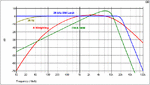
I have an array coming from a digitizer. I do an fft on it and then I calculate the frequency bins and apply a 20kHz low pass filter. The next step would be to apply an ITU-R ARM 2 kHz filter on this array and the filter behaves like the green line curve in the picture. All I know is that the 0 dB point is at 2 kHz and the maximum of 6 dB is located at 7 kHz. The implementation has to done in C++.
 

Attachments

  • FRW-Filt.gif
    FRW-Filt.gif
    11.9 KB · Views: 111

I know I have to have an array of the same length size as the one of my data, but how do I calculate the weighting factors?

The ITU-R ARM is actually 6 dB shifted compared to the ITU-R 468
 

You'll calculate weighting factors for each frequency bin and multiply it. Calculate the power sum, if required.

A numeric representation of the ITU-R 468 filter is given here https://en.wikipedia.org/wiki/ITU-R_468_noise_weighting

- - - Updated - - -

+6 dB is an additional factor of 2 for all table entries. What's the problem with it?
 

That I know, I was just stating, I don't have a problem with it

my only issue is what formula to use to calculate the weighting factors?
 

As I said, a formula for the ITU scaling factor is given in the Wikepedia article. You can also convert the dB values read fom the curve into linear factors.
 

Status
Not open for further replies.

Similar threads

Part and Inventory Search

Welcome to EDABoard.com

Sponsor

Back
Top