Continue to Site

Welcome to EDAboard.com

Welcome to our site! EDAboard.com is an international Electronics Discussion Forum focused on EDA software, circuits, schematics, books, theory, papers, asic, pld, 8051, DSP, Network, RF, Analog Design, PCB, Service Manuals... and a whole lot more! To participate you need to register. Registration is free. Click here to register now.

Issues in PWM and LCD interfacing in PIC16F877A

Status
Not open for further replies.

ragul07

Junior Member level 1
Joined
Aug 1, 2013
Messages
15
Helped
1
Reputation
2
Reaction score
1
Trophy points
3
Location
INDIA
Activity points
83
hey all....
Am trying to generate PWM for a certain constant frequency and the PWM module works fine... :cool:
But when i interface it with an 16x2 LCD and also add some routines to detect the status f PORTA:sad:
The duty cycle of the PWM signal varies and it behaves erratically...!
The program is simple but i does function as desired...

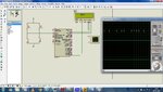
This is my pic with Proteus..
proteus sch.jpg
Here i had attached my code...
View attachment PWM+LCD.txt
 

Hi ragul07,
'flag' variable isn't initialized. Anyway, that should not affect PWM. There is no need to update 'PR2' & 'CCP1CON' registers within while(1) continuously. Try commenting those lines.


Regards,
Raj Gunaseelan
 

There is no need to update 'PR2' & 'CCP1CON' registers within while(1) continuously. Try commenting those lines
Hi raj..
I tried commenting those lines but PWM is not being generated i tried in proteus and also i tried in hardware too...
 

Hi ragul07,

Can you please provide contents of "#include"LCD_Test.h"" file?
 

Hi ragul07,

Cheer up!!

There's nothing wrong in your code. I have tried your code ("LCD_Test.txt") with header file("delay.h") on MPLAB ver2.00. (Hope you have the definition of "DelayMs()" in your "delay.h" file, as I had to edit this file to add this function).
After compiling the code on MPLAB, downloaded it on PIC16F877A in ISIS as per your design. The PWM generated was OK while button(any) was pushed.

For your reference I have attached the image of ISIS runtime image.

However, I have a doubt regarding the Power supply you are providing across both the switches. Can you try using a simple power supply there(as shown in the attached image).
Secondly can you try your code on MPLAB.
 

Attachments

  • PWM_output.jpg
    PWM_output.jpg
    259.1 KB · Views: 56

Status
Not open for further replies.

Similar threads

Part and Inventory Search

Welcome to EDABoard.com

Sponsor

Back
Top