shaikss
Full Member level 4
Hi,
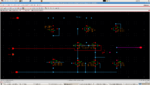
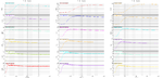
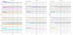
I have used a OpAmp based comparator in one of my designs. The first file is the circuit. Second and Third are the simulation results; the plots of the comparator inputs and output.. In that, the first sub window is the output of the comparator. Second and third sub- windows are the positive and negative input of the comparator. Though I am varying the inputs to the comparator, I don't see the expected behavior. Though inputs are varying around 1V and there is a significant difference between their inputs, my output is always around 500mV. Can you pls help me out why it is behaving so?
I have used a OpAmp based comparator in one of my designs. The first file is the circuit. Second and Third are the simulation results; the plots of the comparator inputs and output.. In that, the first sub window is the output of the comparator. Second and third sub- windows are the positive and negative input of the comparator. Though I am varying the inputs to the comparator, I don't see the expected behavior. Though inputs are varying around 1V and there is a significant difference between their inputs, my output is always around 500mV. Can you pls help me out why it is behaving so?