Continue to Site

Welcome to EDAboard.com

Welcome to our site! EDAboard.com is an international Electronics Discussion Forum focused on EDA software, circuits, schematics, books, theory, papers, asic, pld, 8051, DSP, Network, RF, Analog Design, PCB, Service Manuals... and a whole lot more! To participate you need to register. Registration is free. Click here to register now.

Isolated phase control using SCR

Status
Not open for further replies.

dmta

Member level 2
Joined
Mar 25, 2013
Messages
52
Helped
0
Reputation
0
Reaction score
0
Trophy points
1,286
Location
Earth
Activity points
1,650
Dear all,

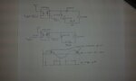
I'm trying to use a SCR for a phase control application. I have tried out the first circuit but I am not getting expected results. The second circuit is the one that I will be using later but due to lack of parts availability I have used the first setup.

Best regards !!!
 

Attachments

  • 20150805_094320.jpg
    20150805_094320.jpg
    1.1 MB · Views: 83

Hi,

You missed to ask a question.

Klaus
 

As I said I am not getting expected results as in the figure. Is the circuit setup correct ??
 

As I said I am not getting expected results as in the figure.
So you want us to guess about your unexpected results instead of telling your observations?

A few guesses are free, however.

I expect circuit #1 to self-trigger without optocoupler input due to dV/dt or leakage current. There should be base-emitter resistors (e.g. 1 Kohm) setting a certain trigger threshold.

In circuit #2, the thyristor will be destroyed by exceeding the reverse gate voltage rating during negative halfwave.
 

Dear FvM thank you for your reply.

I did not have any SCRs to test the second circuit so I used the 1st setup.

I did the testing yesterday with the 1st setup with the load on the low side but did not save any photos of the oscilloscope screen. However I will draw some waveforms that I got.

If I add a diode along with the opto triac will that be adequate? I cannot test it now because I am out of the lab.

I looked up in the internet but failed to find a setup where they use opto isolators to drive a SCR. Can you please tell me how one would normally do it ?

Thank you.
https://obrazki.elektroda.pl/4413104100_1438763452.jpg

- - - Updated - - -

By using a diode I meant something like this
https://obrazki.elektroda.pl/5507377900_1438763706.jpg
 

To start backwards, the series diode for thyristor circuit gonna be O.K.

I understand that the sketched waveform is meaned to describe your present observations. The smaller output before trigger could be explained as leakage, see my previous suggestion. There's however no way to get a full negative half-cycle across the load with the shown circuit #1. Something must be different.
 

the base emitter junction of the 2N3904 must be going into zener mode during the negative half cycle.

The diode, to be clear, must be added at the ouput of the optotriac, to apply a trigger signal only during the positive half cycle.
 

Status
Not open for further replies.

Part and Inventory Search

Welcome to EDABoard.com

Sponsor

Back
Top