Continue to Site

Welcome to EDAboard.com

Welcome to our site! EDAboard.com is an international Electronics Discussion Forum focused on EDA software, circuits, schematics, books, theory, papers, asic, pld, 8051, DSP, Network, RF, Analog Design, PCB, Service Manuals... and a whole lot more! To participate you need to register. Registration is free. Click here to register now.

isolated 1 wire slave

Status
Not open for further replies.

pranam_gharat

Newbie level 3
Joined
Sep 21, 2010
Messages
4
Helped
0
Reputation
0
Reaction score
0
Trophy points
1,281
Activity points
1,314
hi ,

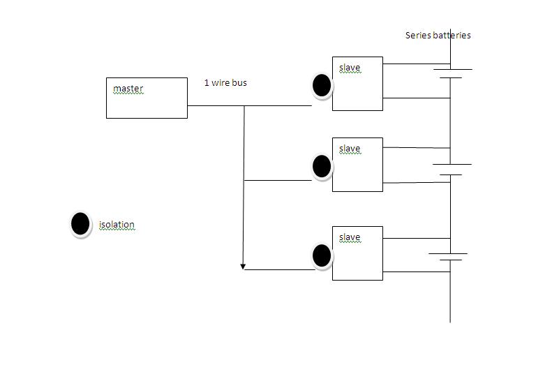
i am doing battery stack monitoring project using DS2438 1 wire battery monitoring ic.

my code is working fine with multi slave.only problem is slave to slave isolation because i cannot common ground.

please suggest me circuitry between micro controller and each slave.

my basic circuit is


<MICROCONTROLLER>-----1wire------<ds2438>------<BATTERY 1>
|
|
| ----<DS2438>---<BATTERY 2>
|
|
|
|
| ----<DS2438>---<BATTERY N>


*ALL BATTERIES ARE CONNECTED IN SERIES.


Thanks and regards,
pranam.


thanks for your replay,

but i think i need slave side isolation as per uploaded image .

may be i required 4 line i:e 1)vcc 2)gnd 3)tx 4)rx.

it can be done using your suggested scheme,but will it handle multiple slave and also which optocoupler should be selected.

also should i go with normal 1wire protocol with separate line for tx and rx or should i go for uart serial protocol(but i doubt it will handle multislave.

thanks and regards,

pranam
 

I can't help with this particular problem but I have something similar in use here which might give useful ideas...

I use several DS18B20 1-wire sensors which are physically spaced over more than 1000 sq metres of area. What i do is use a small PIC (10F202) located immediately next to the sensor and it's firmware talks to the sensor using 1-wire protocol and talks to the cable using bi-phase serial data. I use bi-phase to minimize radiated and induced interference from the cable. It sends at 1200 Bauds which is decoded by a normal UART back at the control box. I'm suggesting this method because it is much easier to isolate normal serial data than 1-wire because the pulse (bits) length is constant.

The biggest probem I can see with mointoring individual batteries in series is if one of them shorts or goes open circuit, it can leave the others with excessive or even reversed polarity and you would have to cater for that happening. It would be more sensible to use one monitor and switch it's input to the different battery junctions in the chain, using appropriate attenuators to ensure the voltage stayed within safe limits.

Brian.
 

Yo can use relays to connect batteries in series one by one. Relays can cope with slow sample rate.


will this scheme work??


please suggest.


regards,
pranam

---------- Post added at 10:27 ---------- Previous post was at 10:23 ----------

i am using relays in another similar circuit.

but scanning tie required high.
 

Unfortunately no, it won't.

The 1-wire protocol is bi-directional so the measurement end needs a path to send signals to the sensor.

In very basic terms this is how 1-wire works, you will see why it has to be bi-directional:

1. The data line is pulled high by a resistor so that the sensor or the master can both pull it low. They can only pull low, they never drive the line high.
2. Master pulling the data line low for a long pulse makes the sensor reset and alerts it to the arrival of a command.
3. The sensor pulls the data line low to acknowledge it has reset.
4. The master sends a series of long or short pulses, each being one data bit, to the sensor to tell it what to do. It's a bit like Morse code!
5. The master sends short pulses to the sensor and the sensor responds by either doing nothing or extending the length of the pulse to send the reply data back.

So without the master being able to send pulses outbound it can't reset or send a command to the sensor and it can't clock the bits of the reply back in again.

Brian.
 

If you can supply the dc externally
So without the master being able to send pulses outbound it can't reset or send a command to the sensor and it can't clock the bits of the reply back in again.
Two optocoupler are used back to back, upper for Tx and lower for Rx. It is easy to supply dc from battery under test otherwise FvM has posted a good solution which also provides isolated dc power supply for slave drive. You can try with different available components other than specified.
 

The trouble with using the two opto-couplers is that it is no longer a 1-wire interface, it requires one transmit line and one receive line to the host. It may work if that is acceptable but I have reservations about the speed requirements being met and the low current in the receive LED. The LED current, ignoring the load of the sensor which makes matters worse, is (VDD - Vled)/(R510+R511) = (5 - 1.4)/2000 = 1.8mA. The data sheet recommends no less than 6.3mA.

It is also a very expensive way of measuring three voltages !!

Brian.
 

Hi,
Did you get the answer for remaining battery capacity using that ICA register? Actually i am getting 0x00 value in that register so i am unable to calculate remaining battery capacity. Please help me for that.
Thanks
 

Status
Not open for further replies.

Similar threads

Part and Inventory Search

Welcome to EDABoard.com

Sponsor

Back
Top