Continue to Site

Welcome to EDAboard.com

Welcome to our site! EDAboard.com is an international Electronics Discussion Forum focused on EDA software, circuits, schematics, books, theory, papers, asic, pld, 8051, DSP, Network, RF, Analog Design, PCB, Service Manuals... and a whole lot more! To participate you need to register. Registration is free. Click here to register now.

IR2110 out of service in less than a second(BLDC circuit)

Status
Not open for further replies.

Omar El Kelany

Newbie level 6
Newbie level 6
Joined
Nov 29, 2012
Messages
12
Helped
0
Reputation
0
Reaction score
0
Trophy points
1,281
Visit site
Activity points
1,377
I am working on BLDC motor driver...using three ir2110 with igbt HGTG30N60C3D...motor is around 400W ..48volt...Boot strap cap. 100uf(big i know).
I tried first to run without hall but couldn't adjust it to run properely...kept misfiring and shaking...so i decided to use hall sensors for better control...i wrote the code..tested the sequence and sure no problem with that...the problem is that the motor rotates for less than a second and one ir2110 is damaged...if i try to buzz across the gate and emitter..it gives a buzz(short circuit) ..if i remove the damaged ir2110 and buzz no buzz, if i replace with a new one...also no buzz, can't figure out the reason why ir2110 is damaged every time. tried with frequency about 35 hz and 500 hz..with duty cycle ranging from 20% to 60%
so i want to ask about
1)what happens if the bootstrap is too large
2)what can cause such problem to happen

Attached half bridge "as i use three half bridges"
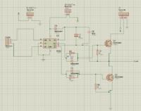
 

I would replace your motor with three 1K resistors wired as a Y. This way you can monitor the various wave forms safely, to see what the problem is. It could be that the peak current is just too high for the FETs. Have you measured the inductance of the motor coils?. Does your wave form ramp up in speed, so the motor magnets can lock on to the field?
Frank
Thanks for your reply.....
1)i would try that resistor connection (y) ...
2)for the FETs you mean those at high side drive... i think that may be a problem...should i increase the Rgate then?? ...or get faster diodes!! or both
3)how would measuring inductance help me sove the problem
4)you said "Does your wave form ramp up in speed, so the motor magnets can lock on to the field?"
can you explain this more please...i don't get it...but the motor never really run..less than 1 complete cycle(360 egree) and ir2110 gets damaged

- - - Updated - - -

i used schottky diodes....now that i have replaced the schottky diode (that one between the 15volt and boot strap cap.) the ir2110 didn't get damaged (i think) but got hot, any suggestions!
 

The IR2110 is not a particularly high speed device, especially if it is driving large loads, how about an emitter follower buffering its outputs - this should reduce dissipation in the device.
 
You have generated a rotating magnetic field, so at a given instance the rotor is attracted to one coil, but if the field changes direction before the rotor has moved very far, the reversal of the field repels the rotor. So the motor never runs. If you start the oscillator at a low frequency, then the rotor can lock on to the field, the motor rotates and the speed can then be ramped up.
Frank
 
your bootstrap capacitor is charged through your load.

charging time = T = C * R = bootstrap capacitor * load resistance

if the capacitor, or the load resistance is too high, your system will be unable to operate at the frequency you want

for exemple with 1k load:

T = 100uF * 1000ohms = 100ms

with 500 hertz you will need 1/500 = 2ms period time, so ~0.7ms rising ... it is impossible for your circuit to switch on/off so fast.


you need the reduce your required charging time by changing bootstrap capacitor or load resistance.
Sorry, but the considerations are completely wrong.

bootstrap capacitor * load resistance is a discharge rather than a charge time constant. It matters in so far that the bootstrap voltage can drop below the undervoltage-lockout level if the high side on-cycle is too long, which is a completely different problem. The purpose of the 1k gate resistors is questionable, they haven't been suggested in any manufacturers datasheet or application note as far as I'm aware of. You might consider to get rid of it and use a smaller bootstrap capacitor. The only thinkable justification for gate resistors is for MOSFETs with a very low threshold voltage which might conduct at a boostrap voltage level when the IR2110 isn't yet able to pulldown the gate to inactive state.

A large bootstrap capacitor involves a problem of large peak currents during startup, a diode series resistor of a few ohms should be considered in this case. A large bootstrap capacitor doesn't bring up problems once it's charged, only the energy amount consumed during high side active phase has to be delivered during next low side phase and it doesn't depend on the capacitor size.
 
  • Like
Reactions: cdez

    cdez

    Points: 2
    Helpful Answer Positive Rating
thanks for correcting me
For the 1k gate resistor I've found this explanation from a blog: https://tahmidmc.blogspot.fr/2012/10/magic-of-knowledge.html
It prevents accidental turn on of the MOSFET by external noise usually at startup when the gate is floating. The MOSFET may sometimes turn on with a floating gate because of the internal drain to gate "Miller" capacitance. A gate to source resistor acts as a pull-down to ensure a low level for the MOSFET. I have had MOSFETs blowing up in high voltage circuits, without the resistor in place. In most of the commercial power supplies / inverters I have seen, there is a 1k resistor used.
 
Get rid of the 1K on the high side.. It causes slow decay of boost cap and results in the low side having massive surge currents at much higher than 50Hz rates. Surge depends on Vout swing, over RdsOn and ESR of Cap.

added peak Power dissipation on low side MOSFET is V² / RdsOn *tPW50 * f from boost charge spikes unless ESR of Cap is significant ( near equal or greater.)

We're talking full voltage here not just the small ripple caused by 1K decay.
But the current duration is tPW50 is limited for the time to restore the voltage to peak. and repeated at switching rate f.


Then you can relax value of C_boost
 

sorry guys for late responding...and thanks so much for your concern.....
In fact the problem was my arduino...it gave 5v before connecting supply to the driver circuit...but then voltage drops
i tried another arduino "and i believe fast diodes really helped" ...motor worked fine...the ir2110 didn't get warm even...everything was perfect....but this is at no-load
By mistake while trying a one of the Hall connections was cut...leading the motor to shake...and that damaged an IR ....So motor shaking leads to surges leading to IR damage??
would you tell me please about problems i may face at loading the motor...specially at starting so that i can avoid damaging more IRs :D
and thank you Tahmid....i learned really much from his blog

- - - Updated - - -

You have generated a rotating magnetic field, so at a given instance the rotor is attracted to one coil, but if the field changes direction before the rotor has moved very far, the reversal of the field repels the rotor. So the motor never runs. If you start the oscillator at a low frequency, then the rotor can lock on to the field, the motor rotates and the speed can then be ramped up.
Frank

The hall sensors don't solve this problem??
 

For the 1k gate resistor I've found this explanation from a blog: **broken link removed**
Yes I know it. In fact the gate can only float up to the IR2110 supply + 0.7V (low respectivly high side supply) when the supply voltage is too low to activate the gate driver transistors. This can happen in a supply voltage range up to 2.5 or 3 V. So only MOSFET with a low gate threshold are potentially affected.

The other point is that you can doubt if the pull-down resistor is effective at all. The gates won't simply float high on it's own, they are driven by Cdg when the other switch transistor is activated. A 1k resistor can't sink sufficient current to hold the gate low in this situation.
 

Regardless of everything that has been advised, I would first heed Chuckey's advice: substitute the motor with a resistive "dummy" load for troubleshooting.

This technique has saved me of countless grief every time I've built a motor driver or Class-D audio amp.
 

Status
Not open for further replies.

Similar threads

Part and Inventory Search

Welcome to EDABoard.com

Sponsor

Back
Top