Continue to Site

Welcome to EDAboard.com

Welcome to our site! EDAboard.com is an international Electronics Discussion Forum focused on EDA software, circuits, schematics, books, theory, papers, asic, pld, 8051, DSP, Network, RF, Analog Design, PCB, Service Manuals... and a whole lot more! To participate you need to register. Registration is free. Click here to register now.

IR2110 not working in hardware.

Status
Not open for further replies.

Bikalpa001

Newbie level 3
Joined
Jan 21, 2015
Messages
3
Helped
0
Reputation
0
Reaction score
0
Trophy points
1
Activity points
28
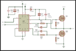
This is the circuit that I am working with at the moment. However, I am not using +300V on the MOSFETS, but using only 12 volts.

The MOSFETS we are using are p75nf75.

I need to make 3 such circuits for U, V and W phases.

I have used In5408 in place of D1 and In4001 in place of d2 and d3.

I have used a capacitor of 1 uf/63v for c1.

The resistor I have used for R1 and R2 are 33 ohms and for R4 and R5 are 1.5k ohms respectively.

Please suggest me the portion I went wrong. I am not getting the desired output.


i need to actually drive a 36 volts 250 watt motor but i was looking forward to first make this circuit and test it with the CD_ROM motor.

I would appreciate your help.
 

Attachments

  • ir2110.png
    ir2110.png
    52.2 KB · Views: 64

Thank you treez.
I will try that.
anything else i should be looking into?
 

Hi Bikalpa001,

What is the frequency that you are using?

I doubt if your bootstrap has got something to do with it.

Do you mind checking it with other capacitor 22uF or 47uF based on your frequency and tell us exactly what is the issue?
Also use UF diodes as treez said.

Regards
 

Hello emaniac,
i have used 1MHz in microcontroller and my pwm is about 512 Hz.
i again tried the circuit using a 10uF/50V capacitor on vcc and com.
and 10 ohms resistor replacing the 33 ohms. and also using a 1 uf capacitor on vdd and gnd
and 1 uf capacitor on vs and vb.
but the ic got heated and the circuit did not work too...


do i have to replace the 1n5408 as well?
is using a resistor between gate and drain similar in purpose to keeping diodes parallel to the resistors?

thank you
 

you really need diff probe to scope the high side fet gate-source voltage, and to scope the voltage across the bootstrap cap.
Doing that without diff probe is bad news.
 

For low frequencies you can use around 47uF bootstrap capacitor.

Resistor between gate and drain?
If u have your PCB done, can u please post the schematic of your circuit. In case the previous image was not the exact design of yours, it would be helpful posting your schematic.

Regards
 

The lower devices must be turned on for some portion of the time periodically in order the charge the bootstrap caps to allow the top devices to be fired, if you have overlapping gate drive signals or too low a dead time you can damage the fets and hence the 2110's, also 600v ultra fast diodes are preferable.
 

you could always try simulating it....you cant simulate the ir2110, but you can simulate eg the LTC4440 in LTspice which is a similar bootstrap operation.
Also, if youre layout is bad you get other problems too...for example the VS pin can ring below ground, and you really need a suitable ultra fast HV diode from VS to GND.......cathode to VS.

also, it is standard to add protection zeners on the gate-source of each fet.
Also a series say 5r1 resistor in series with the bootstrap diode to limit inrush.

Which differential probe are you using also? You need to scope the upper fet GS and the bootstrap cap voltage....if you are doing that without diff probe then you are putting gnd of probe onto a node with high dv/dt, which cause you problems.....differential probe is needed.
 
Last edited by a moderator:
Status
Not open for further replies.

Similar threads

Part and Inventory Search

Welcome to EDABoard.com

Sponsor

Back
Top