Continue to Site

Welcome to EDAboard.com

Welcome to our site! EDAboard.com is an international Electronics Discussion Forum focused on EDA software, circuits, schematics, books, theory, papers, asic, pld, 8051, DSP, Network, RF, Analog Design, PCB, Service Manuals... and a whole lot more! To participate you need to register. Registration is free. Click here to register now.

Inverter Battery voltage measurement

Status
Not open for further replies.

archusvijay1

Member level 3
Joined
Mar 12, 2014
Messages
61
Helped
0
Reputation
0
Reaction score
0
Trophy points
6
Activity points
553
Hi,
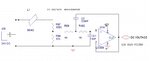
we are trying to implement a system to measure the battery voltage of an inverter. the battery voltage is passed through a low pass filter and then the voltage i measured using pic18 adc pin.and then 500 sample voltages are taken and average voltage is calculated, but it will not get any exact voltage.What is my problem?how can i resolve it? is it FIR or IIR digital filter is needed?

please help to solve this issue?
thanks and regards
 

Attachments

  • Capture.JPG
    Capture.JPG
    50.5 KB · Views: 57

How much time the fully charges battery take to discharge to 10.8V when inverter is on full load ? why filter is used. Can't you use a voltage divider and measure the voltage ?

Divide voltage like 24V - 5V and 5V (for adc) and measure the 5V voltage. In code convert 5V adc input to 24V. If needed take 20 or 50 readings and sum it and then divide it by number of readings and then convert it to 24V scale and use it.

Post your PIC circuit. How are you displaying the Battery Voltage ?
 

Circuit is correct. Should work.
500 samples is requere devide math operation. 512 will be better - only bit shift will be needed wich is much faster. But anyway, I suspect your program incorrect reading the ADC input. Explanation like a "don't working" in not clear. What is a actual voltage on input on ADC? What is the value readed by ADC? What is a value you got after 500 samples? Also, provide you code if you expect for real help.
 

is it FIR or IIR digital filter is needed?

A digital LPF is of no use if your signal itself is noisy.
Is there enough filtering on the input side of your attenuator?
Is there any noise induced on the DC line when the inverter is turned on? If yes, then the ripple/noise should be of the same frequency as that of the switching frequency of the inverter.

You have designed a Sallen-Key LPF, which is a 2nd order active filter. It's cutoff frequency should be atleast 10 times less than that of the switching frequency of the inverter, for proper noise rejection at the output.

If all these things are taken care of, then there might be a problem in your code, which you should post here if you want to seek further help.
 

1. If Battery -Ve and your system -Ve is same then use simple low pass RC filter after potential divider and take 10 samples only.

2. if not use use Instrumentation amplifer
 

Hi,

To implement a digital filter (taking 500 samples and average...is a digital filter) needs a known and fixed sampling frequency.
Everything else is try and error and may work now, but may fail the next day.

Why?
Only with a fixed and known sample frequency you are able to calculate an analog filter (called: anti aliasing filter).
The analog filter should attenuate all frequencies above half of the sampling frequency (nyquist) to an uncritical level.
This safely prevents alias frequencies...and only then the digital filter can safely work.

Klaus
 

Status
Not open for further replies.

Similar threads

Part and Inventory Search

Welcome to EDABoard.com

Sponsor

Back
Top