Continue to Site

Welcome to EDAboard.com

Welcome to our site! EDAboard.com is an international Electronics Discussion Forum focused on EDA software, circuits, schematics, books, theory, papers, asic, pld, 8051, DSP, Network, RF, Analog Design, PCB, Service Manuals... and a whole lot more! To participate you need to register. Registration is free. Click here to register now.

Interfacing Transmitter and receiver to PSoC

Status
Not open for further replies.

Pradeepbp

Junior Member level 2
Joined
Sep 21, 2013
Messages
23
Helped
9
Reputation
18
Reaction score
9
Trophy points
3
Location
Kerala
Visit site
Activity points
214
HI,
We re doing a project of displaying messages in LCD module using PSoC. We will input the message from system,from where PSoC takes the message and sends to RF transmitter and transmitter transmits the message. At receiving end, receiver gets the message and sends to another PSoC to display in LCD.
KIT: Cypress evaluation kit PSoC 1
Tx: RF tx 433MHz
Rx: RF Receiver 433MHz

question:
1. How to interface PSoC and RF transmitter/receiver? any particular protocol needs to be followed?
2. Transmitter modulates the message and transmits. At the receiving end, is there anything to worry about demodulating? or the receiver takes care of it?

We don't have the modules as of yet. So did not try it out. After making a solid study on feasibility of project, we are going to order for the modules. So please help.
Let me know if more information is needed.

Thanks!
 

First I would need to know what form the digital signal comes as a "message" to be transmitted. If it is TTL, fine. Otherwise you must specify the min/max voltage and source impedance.
Next you need to know what signal format is required to modulate the "RF TX 433 MHz". If the both formats are compatible, you can connect the digital (e.g.TTL) output from your message generator directly to the TX input. And also from the RX output to message display input.
If there are differences in amplitude, like not TTL but differential or other kind, then you must design an interface to match message signal flow.
Take care not to overdrive any of the inputs. Mostly if the voltage output is smaller than required as input, you can try the combination, it may work.
 

Hi,
sorry for my late reply.
We did little bit of digging on what we need to do..
1. We will send message from PC to PSOC through hyperterminal-RS232 connection. PSOC has onboard RS232 interface, so no need of MAX232 IC.
We make use of UART or Rx8 user module available in PSOC designer to receive data from PC.
2. The message from PSOC is to be transmitted through a RF transmitter. Here we dont have to modulate. Data we put at RF-transmitter pin is received at the RF-receiver pin. Modulating and de-modulation is taken care by RF Tx and Rx IC.
3. This data from RF-receiver is collected in another PSOC and displayed on LCD.

I am struck in the part where I have to tap in the data from Rx pin in J13 of PSoC and display it on LCD.
For this I have to connect a wire from Rx pin of J13 to any port pin and the port pin is connected to Rx block in PSoC

Im trying the APT(application programming interface) from Rx8 datasheet but i don't get the expected data.
I tried using 'CHAR RX8_cGetChar(void)' and the example code in datasheet but none works for me.
I am not sure if there is data coming out from Rx pin in J13. that pin seems to be high always.
Can anyone help me?

It is always good to check the J13 signal with an oscilloscope. If it shows no data or locking to a fixed level, you will have to find what to do. Simple receivers utilize superregen RF stage and are sensitive to RF too high or too low.
Without a schematic it is difficult to say what best to do. I used a similar TX-RX combination and the RF tuning coil had to be fine-tuned with a plastic screwdriver for a good transmission of data signal.
Also check TX and RX antenna to be set correctly, also their polarization. Possibly no obstacles in the way...
 
Hi,

J13 terminal is sending data correctly. when we send data from PC to PSOC through RS232 and take the data from J13 and display it on LCD. it works but when i put RF Tx-RX in place of the wire then its not working.

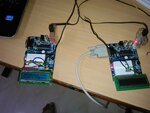
Here's a snap.
DSC_0024.jpg
Left PSOC is the one which gets data from receiver. you can see receiver chip that kit.
Right PSOC kit is only used for RS-232 and Max232. We are connecting J13 terminal directly to RF-Tx. PSOC chip is not used here.
When we connect a wire in place of Tx-Rx, correct data can is seen on LCD. but with Tx-RX module, we are getting only garbage. Receiver keep on detecting some junk even when Tx is not sending anything and even when Tx is off.
I checked Tx-Rx by programming to send a stream of pulse Tx and detecting those pulse in Rx.I used a CRO for this. output voltage is 5V of the receiver. So Tx-Rx are working correctly.

Can you tell how to make my Rx not to send junk when im not sending any data to Tx?
 

Again, without a schematic it is difficult to advise. Many receivers output noise when TX is not active. I would try to make some squelch circuit. Often a pull-up resistor like 10 kOhms at the receiver output can kill the random output, sometimes one must find a suitable point in the receiver before the output.
 
Hi,
My groupmate just replaced those Tx and Rx with new one and they are working fine. Just as needed. No squelch circuit needed.
What I did not understand is, the previous Tx-Rx pair successfully send pulse when i tested them in CRO. But did not send data correctly. Don't know what happened. I do not worry abt it much.
Thanks for the help!!! :)

Do you know what is the output voltage level of MAX232 ? If its less than 5V then we can pull is to 5V and increase the range of my R module..
 

Status
Not open for further replies.

Part and Inventory Search

Welcome to EDABoard.com

Sponsor

Back
Top