Continue to Site

Welcome to EDAboard.com

Welcome to our site! EDAboard.com is an international Electronics Discussion Forum focused on EDA software, circuits, schematics, books, theory, papers, asic, pld, 8051, DSP, Network, RF, Analog Design, PCB, Service Manuals... and a whole lot more! To participate you need to register. Registration is free. Click here to register now.

Integrator design problem because of 0.5V dip at the start

Status
Not open for further replies.

girih192002

Full Member level 2
Joined
Aug 4, 2007
Messages
130
Helped
19
Reputation
38
Reaction score
11
Trophy points
1,298
Location
India
Activity points
2,115
Hi,

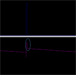
I am designing simple integrator. When Reset is going in off state. integration is starting.When Integration is started. There is dip from 2.5 V to 2 V after that integration of injected current is starting.
I did not understant why there is dip of 0.5 V.

Please, help me to understand phoenomenon. Please, go through an attached simulation waveform.
 

Attachments

  • integration.png
    integration.png
    11.2 KB · Views: 82

Re: Integrator Design Problem

I still don't know the exact switch and signal sequence.

If the voltage step is a reaction to an input current step, we can expect insufficient integrator loop gain and high output OP output resistance.
 

Re: Integrator Design Problem

I still don't know the exact switch and signal sequence.

If the voltage step is a reaction to an input current step, we can expect insufficient integrator loop gain and high output OP output resistance.

Hi FvM,

I am sorry for incomplete information. I have rectified the bug. Actually, Vcm was 2.5 V and I have given Offset = 2 V. so, There is pull down of 2.5 V to 2 V to start Integration.

Thank you FvM
 

Status
Not open for further replies.

Part and Inventory Search

Welcome to EDABoard.com

Sponsor

Back
Top