Continue to Site

Welcome to EDAboard.com

Welcome to our site! EDAboard.com is an international Electronics Discussion Forum focused on EDA software, circuits, schematics, books, theory, papers, asic, pld, 8051, DSP, Network, RF, Analog Design, PCB, Service Manuals... and a whole lot more! To participate you need to register. Registration is free. Click here to register now.

integrated antenna with AMC produce negative gain

Status
Not open for further replies.

yaser2016

Newbie level 4
Joined
Feb 8, 2016
Messages
6
Helped
0
Reputation
0
Reaction score
0
Trophy points
1
Activity points
52
Dear all,

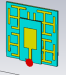
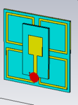
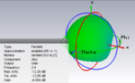
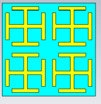
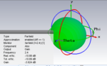
I have designed simple microstrip antenna at 2.4GHz and I check its gain which has 1.488 dB when I integrate the antenna with AMC it gives me a negative gain

Do anybody had experienced such this problem or has idea to solve it can help me?

Thanks in advance
 

Welcome yaser2016,

Are you measuring at the same frequency once you introduce the AMC? Most likely, the antenna's resonant frequency has shifted.
 

Thanx a lot for your replay

Yes
I design the antenna and AMC separately at 2.4GHz, then I integrated them and I used foam with thickness of 1mm as spacer between them to avoid short circuit
when I simulate them using cst, the frequency is shifted as you mentioned. I tried to modified the patch of the antenna until I got to 2.4GHz. when I got it I realized that the directivity in positive while the gain is negative
thanx in advance
 

Most likely then your AMC is doing something to prevent the fields from being radiated, such as the incorrect type of parasitic coupling (electric dominating instead of magnetic or vice-versa).
 

Thanx a lot
I have tried anther AMC design and I integrated with antenna, still same problem negative gain

I attached the PIC of design

could you please suggest me to overcome this problem
if you need the cst file i will give you

Your cooperation is highly appreciated
 

Attachments

  • Antenna with  I shaped AMC.PNG
    Antenna with I shaped AMC.PNG
    6.4 KB · Views: 145
  • antenna with square loop AMC.PNG
    antenna with square loop AMC.PNG
    6.6 KB · Views: 146
  • Gain of I  shape AMC.PNG
    Gain of I shape AMC.PNG
    19.5 KB · Views: 159
  • I shap AMC.PNG
    I shap AMC.PNG
    5.1 KB · Views: 116
  • square AMC gain.PNG
    square AMC gain.PNG
    18 KB · Views: 119
  • square loop AMC.PNG
    square loop AMC.PNG
    4.1 KB · Views: 122

looks like you are designing patch antenna. patch antennas has ground plane underneath and those are Left hand circular polarized antenna (LHCP). you peak gain will be right above you patch antenna! i dont know what AMC stands for but i assume another PCB board. having another metal underneath patch antenna should not effect the patch because it has ground plane underneath of it! your results looks suspicious!
 

Thanks a lot

Yes I am designing patch antenna, when I simulate it separately, it gives me positive gain but when I integrate it with AMC give me negative gain instead of improving it and reduce the backlobe .

AMC stand for artificial magnetic conductor surface that have two interesting properties that do not occur in nature. First, AMC surfaces have a forbidden frequency band over which surface waves and currents cannot propagate, making them useful as ground planes and planar or waveguide type filters. Second, AMC surfaces known as high surface impedance which mean that AMC surface varies continuously from +180◦ to −180◦ relative to the frequency, and crosses zero at just one.

Now I am confusing why negative gain is even I tried different design.

any idea or solution that can help me to overcome this problem

Your cooperation is highly appreciated
 

I'm a tad suspicious of your AMC design - the unit cells are very large compared to the size of the patch. This may have something to do with it -- you can check if this is an issue by moving the antenna around to different locations on the surface (keeping the same distance to the AMC).

Additionally, are you saying that the patch antenna has its own (solid) ground plane, even when placed above the AMC?
 

you are trying to employ AMC underneath patch antenna so it will act as reflector which will reflect backlobes and improve mainlobes/directivity/gain. am i correct?

actually i know how to do this but i have patent filed on this!8-O

:thinker:

- - - Updated - - -

will you or your organization will be interested in licensing our patent?
 

Thanx a lot PlanarMetamaterials

Actually, I follow some paper their AMC larger than the patch antenna. i check as you mention by moving the antenna around to different locations on the surface (keeping the same distance to the AMC) but unfortunately still give negative gain

Even i try to replace the antenna horizontally but still same problem.

For the antenna has ground even when integrated with AMC but also now i tried to remove it but no benefit

I got confused regarding my design ,I don’t know what is the problem that let gain negative


her is the paper i referred to it

thanx a lot
 

Attachments

  • 08.11051109.pdf
    703.9 KB · Views: 123
  • 04812233.pdf
    1.4 MB · Views: 115

thanx a lot pragash

just I am a student doing research
 

For the antenna has ground even when integrated with AMC but also now i tried to remove it but no benefit.

Something seems wrong here. The addition/removal of a solid conductor under the antenna should change the behaviour of the antenna. Are you sure everything is set up correctly in the simulation?
 

Status
Not open for further replies.

Part and Inventory Search

Welcome to EDABoard.com

Sponsor

Back
Top