mordak
Member level 5

- Joined
- Mar 8, 2013
- Messages
- 82
- Helped
- 0
- Reputation
- 0
- Reaction score
- 0
- Trophy points
- 1,286
- Location
- Neverland
- Activity points
- 2,134
Hey guys,
I faced a problem with designing integrators and summing block in a continuous time (CT) delta sigma ADC. I have read in several papers and theses that unity gain bandwidth of the opamps in the CT delta sigma, unlike the DT one is less, like 2~3 times than sampling frequency. I tried to find the required bandwidth by using ideal opamps with finite bandwidth (first pole system). I could find the requirement, however, after designing the real opamp according to those specification that I found before, ADC did not work properly. The only difference I could think of was the effect of the input capacitance of the real opamp which I did consider in the ideal one.
After adding two capacitor at the input of the ideal opamp (which has limited bandwidth), saw that the the ADC showed the same behavior as when I used the real opamp. To solve this problem I had to either increase the gain bandwidth of the opamp, or decrease the resistor used in the summing/integrator block. In either case power consumption would be significantly increased, though I saw everywhere that CT delta sigma doesn't need high gain bandwidth for its opamps and the whole ADC consumes less power. The input capacitance of the opamp is about 300fF, which I think is a normal number, but it causes problem and I have to decrease the value of the resistor from 100K to less than 5K to have the summing block work. Does it make sense to say impedance of the input capacitance of the real opamp should be a way more than the resistor used in the summing/integrator block?
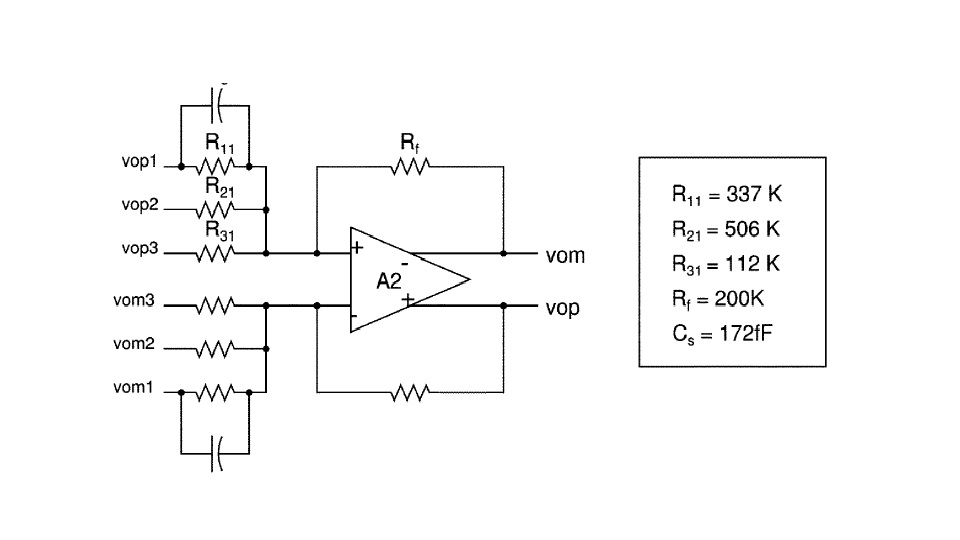
In a part of a paper I attached here, there is a summing block with resistor more than 100Kohm, and sampling frequency of around 3MHz, if what I said above is correct, it means the input cap of this opamp should be less than 50fF! (if we only consider the 100K resistor)
I faced a problem with designing integrators and summing block in a continuous time (CT) delta sigma ADC. I have read in several papers and theses that unity gain bandwidth of the opamps in the CT delta sigma, unlike the DT one is less, like 2~3 times than sampling frequency. I tried to find the required bandwidth by using ideal opamps with finite bandwidth (first pole system). I could find the requirement, however, after designing the real opamp according to those specification that I found before, ADC did not work properly. The only difference I could think of was the effect of the input capacitance of the real opamp which I did consider in the ideal one.
After adding two capacitor at the input of the ideal opamp (which has limited bandwidth), saw that the the ADC showed the same behavior as when I used the real opamp. To solve this problem I had to either increase the gain bandwidth of the opamp, or decrease the resistor used in the summing/integrator block. In either case power consumption would be significantly increased, though I saw everywhere that CT delta sigma doesn't need high gain bandwidth for its opamps and the whole ADC consumes less power. The input capacitance of the opamp is about 300fF, which I think is a normal number, but it causes problem and I have to decrease the value of the resistor from 100K to less than 5K to have the summing block work. Does it make sense to say impedance of the input capacitance of the real opamp should be a way more than the resistor used in the summing/integrator block?
In a part of a paper I attached here, there is a summing block with resistor more than 100Kohm, and sampling frequency of around 3MHz, if what I said above is correct, it means the input cap of this opamp should be less than 50fF! (if we only consider the 100K resistor)