Continue to Site

Welcome to EDAboard.com

Welcome to our site! EDAboard.com is an international Electronics Discussion Forum focused on EDA software, circuits, schematics, books, theory, papers, asic, pld, 8051, DSP, Network, RF, Analog Design, PCB, Service Manuals... and a whole lot more! To participate you need to register. Registration is free. Click here to register now.

input and output ports clarification

Status
Not open for further replies.

electronic_satya

Member level 2
Joined
May 17, 2011
Messages
49
Helped
0
Reputation
0
Reaction score
0
Trophy points
1,286
Activity points
1,662
hi all,

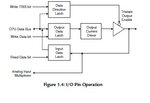
i have this basic clarification about the input and output ports. in general a port can be configured as either input and ouptut from microcontroller can somebody explain this at the transistor level by the transistor diagram. i know that you can make the port high or low by controlling the base of the transistor how the same port can be acheived as input that is the microcontroller should read whether high or low is available at the input how does it know? and how does it remember?

thanks in advance,

regards,
Satya
 

the ports set as input or output using latches and tri-state buffer
check the attached image
from book
programming 8 bit pic microcontrollers in C by martin P.bates
page 13
 

Attachments

  • Untitled.jpg
    Untitled.jpg
    17.5 KB · Views: 90

Hey
I saw some electronic devices which used PIC micro-controller on it and they used same pin as input and output at same time how is that possible?
 

It is very common to have a "pad" module in modern I.C. design library. Besides including both input and output capable circuits there are ESD protection, Schmitt trigger configuration, output drive strength setting, pull-up or pull down resistor, edge polarity detection/latching for interrupt signalling, and voltage level shifting to provide higher voltage I/O capabililty from lower voltage inner core logic. The control lines for these functions are sometimes hard wired to fix a particular function or fed from a programmable latch that allows some of the functions to be changed by the programmer.

Even if all you need is a plain-old input it is easier to just use the library I/O module which in many cases incorporates the actual bonding pad for the IC. It also ensures a consistant, proven ESD and I/O performance to established standards which would be at risk of degenerating into a free-for-all if every designer was allowed to design their own I/O interface.
 
Hi all,

M a newbie.M using Pic16f877a microcontroller to implement port driver.M using Hitech C compiler. I have written d code to initialize the ports.But m facing problem to read the port values and write values to the ports. Please can anyone help me with the logic to read/write to ports.


Thanx in advance
 

Status
Not open for further replies.

Similar threads

Part and Inventory Search

Welcome to EDABoard.com

Sponsor

Back
Top