Fengxuan
Newbie level 2

- Joined
- May 18, 2014
- Messages
- 2
- Helped
- 0
- Reputation
- 0
- Reaction score
- 0
- Trophy points
- 1
- Activity points
- 21
Hello everyone, I am a freshman to HFSS and looking for some help on the simulation on a simple spiral inductor. I want to see how the inductor behaves around 100 MHz.
In fact, my inductor is very similar to the one shown in the tutorial example, which you can find here: **broken link removed**
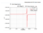
To make things easier, I followed every step in the tutorial and simulated the same inductor and got the same result of inductance like this:

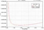
Everything looks right but, if you look carefully, at the low frequency end, the inductance begins to increase. This also occurs in my own inductor simulation. According to the theory, when frequency is approaching to zero, the inductance should approach its DC value. Not sure why here it starts to increase.
I tried with different mesh numbers but it doesn't make any difference.
I tried to increase the boundary dimension--a lot of people here mentioned that the dimension should be wavelength/4. But at 100 MHz, the wavelength is a few meters while the inductor is a few microns. I tried setting the boundary to be 1 m^3 but the simulation never ends....takes too long.
So, anyone have any idea why the inductance increase at low frequency or what should I do to make it right?
Thanks a lot!
In fact, my inductor is very similar to the one shown in the tutorial example, which you can find here: **broken link removed**
To make things easier, I followed every step in the tutorial and simulated the same inductor and got the same result of inductance like this:

Everything looks right but, if you look carefully, at the low frequency end, the inductance begins to increase. This also occurs in my own inductor simulation. According to the theory, when frequency is approaching to zero, the inductance should approach its DC value. Not sure why here it starts to increase.
I tried with different mesh numbers but it doesn't make any difference.
I tried to increase the boundary dimension--a lot of people here mentioned that the dimension should be wavelength/4. But at 100 MHz, the wavelength is a few meters while the inductor is a few microns. I tried setting the boundary to be 1 m^3 but the simulation never ends....takes too long.
So, anyone have any idea why the inductance increase at low frequency or what should I do to make it right?
Thanks a lot!

