Muralidharan
Newbie level 5
I have a situation as below:
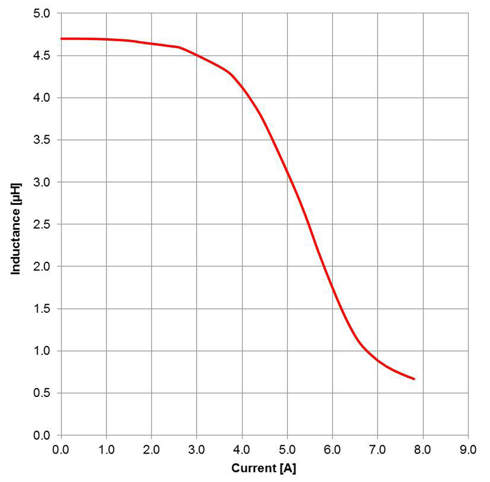
Please see the attachment. I am rising current in inductor from 0 to 4.2A peak over a period of 3.5microseconds as you can see in the attachment. I open the inductor at 3.5 microseconds and derive
an induced back emf of 150V .The value of the inductor is 4.7 micro henry. The particular inductor used has saturation current limit of 3.7A and as you can see, I am driving it beyond saturation current. The inductor is off for close to 150ms and again the cycle repeats .
I weighed the following while driving the inductor beyond saturation limit. Physically, when you are rising current through the inductor , the core saturates and even if you overdrive current through the inductor beyond saturation limit, there will very little further build up of magnetic flux in the core.AT this point in time if you withdraw the current and reduce it to 0 A, back emf will be induced in the inductor due to release of magnetic flux. And such backemf should be the same approximately whether you drive the inductor to saturation limit or even beyond. I have found the circuit giving me what /i wanted ..approximately 150V bakcemf at the end of every 3.5 microsecondsfor more than 2 days but suddenly after 2 days the inductor value seems to have come down..from 4.7 microhendry to 1.2 microhendry and I get much less backemf voltage now.
Though I am aware that I am using the inductor outside the saturation current limit ,
the theoritical question here is as follows:
Case 1. Drive inductor till saturation current (ex 3.7A)is reached..The core saturates .At this time , reduce the current to 0...Back emf will be induced to say V1 volts.
Case 2. Drive inductor to a higher current than saturation limit(say 4.2 A) .This should build saturation level flux only. If after reaching the drive current of 4.2A, if drive current is reduced to 0, what should be the back emf induced? According to me, it should be either V1 volts as in case 1 or a little more . Can there be irreversible changes in the magnetisatin characteristics of the inductor? If you need further clarifications on the question, I can provide the needed clarifications
What is your opinion and why