Continue to Site

Welcome to EDAboard.com

Welcome to our site! EDAboard.com is an international Electronics Discussion Forum focused on EDA software, circuits, schematics, books, theory, papers, asic, pld, 8051, DSP, Network, RF, Analog Design, PCB, Service Manuals... and a whole lot more! To participate you need to register. Registration is free. Click here to register now.

[SOLVED] Improve the S21 of an RF rectifier with a matching network:

Status
Not open for further replies.

Nathan1

Junior Member level 3
Joined
Jun 10, 2021
Messages
27
Helped
0
Reputation
0
Reaction score
0
Trophy points
1
Activity points
207
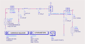
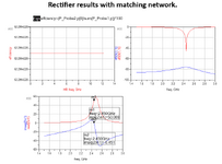
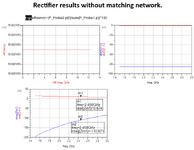
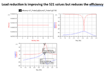
The matching network is well matched at 2.45 GHz and improves the rectifier efficiency but S21 values are still around -80 dB (which should be around 0 to -3dB). The S21 values improve a little bit when I reduce load, but efficiency degrades too much. What can be done to improve the S21? The rectifier circuit and simulation results are attached. Thanks in advance.
 

Attachments

  • rectifier circuit.png
    rectifier circuit.png
    62.8 KB · Views: 76
  • Results with MN.png
    Results with MN.png
    47.4 KB · Views: 70
  • results without MN.png
    results without MN.png
    46.3 KB · Views: 81
  • S21 at small load values.png
    S21 at small load values.png
    48.1 KB · Views: 79

Just a misunderstanding. S21 is meaningless less for a circuit with DC output. If relevant at all, you want S21 of - inf, no RF residuals at DC output.
 
I have written thousand times. S-parameters are small signal parameters and they cannot be used nonlinear circuits. Therefore S21 is almost zero due to Open Circuited Diodes.There is just small junction capacitance but the Diodes are Open Circuit.Simulator drive the circuit with very small negligible voltages and currencts.( no sense at all )
If you would check the Power Gain, use Large Signal S-Parameters Simulation with appropriate driving level as same as HB level.
HB will also give the Power Gain, why don't you use this feature ?
Thanks a lot, I am using LSSP and HB in my actual circuit. It was just a misunderstanding about S21.
 

Status
Not open for further replies.

Part and Inventory Search

Welcome to EDABoard.com

Sponsor

Back
Top