Continue to Site

Welcome to EDAboard.com

Welcome to our site! EDAboard.com is an international Electronics Discussion Forum focused on EDA software, circuits, schematics, books, theory, papers, asic, pld, 8051, DSP, Network, RF, Analog Design, PCB, Service Manuals... and a whole lot more! To participate you need to register. Registration is free. Click here to register now.

Impedance matching using T and Pi pads

Status
Not open for further replies.

neazoi

Advanced Member level 6
Joined
Jan 5, 2008
Messages
4,122
Helped
13
Reputation
26
Reaction score
15
Trophy points
1,318
Location
Greece
Activity points
36,951
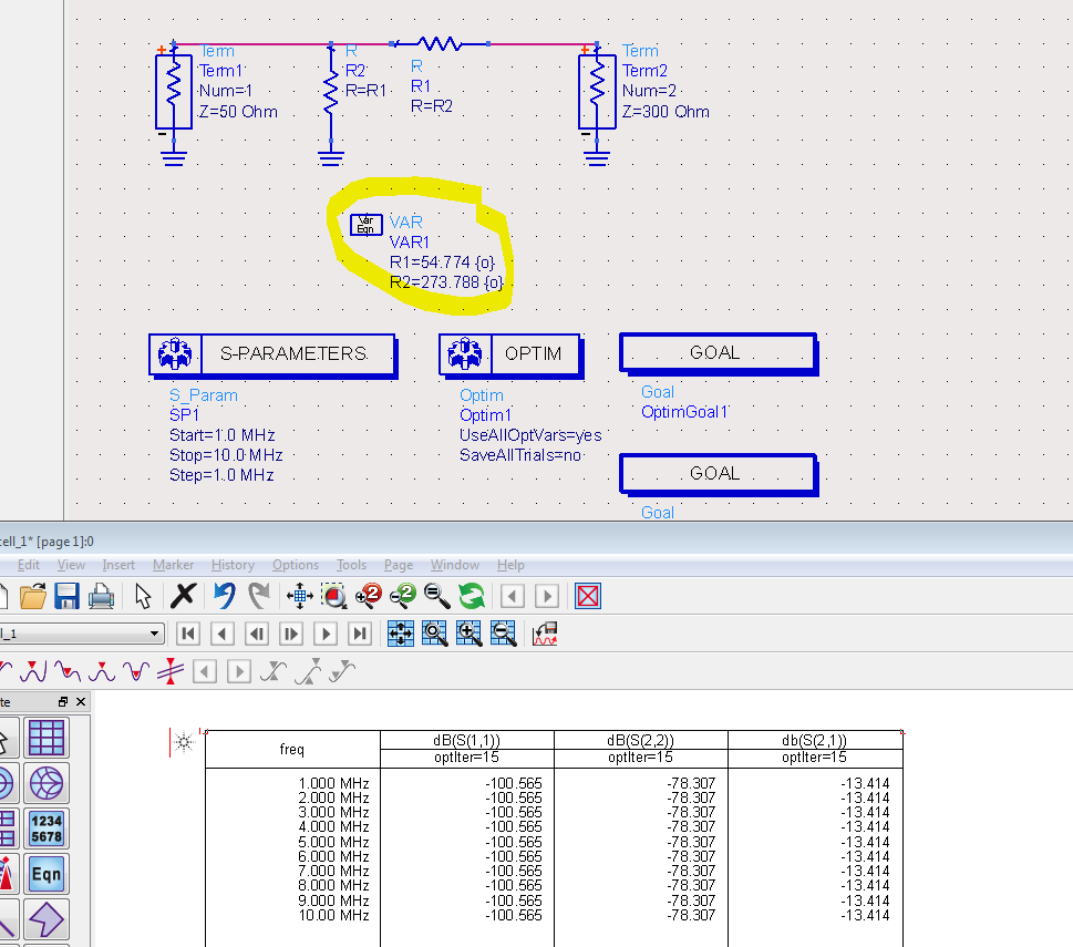
Hello, I am onto the design of an RF mixer that requires a 50R RF in and a 300R LO in.

My LO has an output impedance of 50R.

How can I match this 50R to the mixer input, which expect to "see" a 300R impedance?

I would like to use only resistive pads due to their broadband nature.

The L-pad cannot be used because the input impedance is lower than the output.

I have seen these:
https://www.electronics-tutorials.ws/attenuators/t-pad-attenuator.html
https://www.electronics-tutorials.ws/attenuators/pi-pad-attenuator.html

These seem that can match a lower impedance input to a higher right, am I right?
Which one would you choose?
 

Use 2:1 Broaband Transformer to match 300 to 50 Ohm with reasonable loss.( see Mini Circuits or others).
Resistive Pads are Broadband but pretty lossy.
 
  • Like
Reactions: neazoi

    neazoi

    Points: 2
    Helpful Answer Positive Rating
Use 2:1 Broaband Transformer to match 300 to 50 Ohm with reasonable loss.( see Mini Circuits or others).
Resistive Pads are Broadband but pretty lossy.

Yes I am aware of the losses.
I just need to know if what I want to do can be accomplished this way, regardless of the losses.
 

Last edited:

Pi match attenuators at all ports would help especially in diode mixer case.
Active mixers generally don't need very good (and wideband) 50 ohms terminations at the ports.
The most important port that requires good termination to get good mixer IMD, is the IF port.
 

LO power, at least in a passive mixer, wants to be pretty high to drive the mixer. So putting in a large value attenuator just to "match" the amp to the lo port sounds counterproductive. Can you place the amplifier physically right at the LO port, so there will be no standing wave with a lengthy transmission line between the two. That way you will get ok power transfer and no big ripples in the LO power vs. frequency.

if not that, then:

at low frequencies (< 1 GHz) you can probably just use a wirewound transformer.

At higher frequencies, maybe a quarterwave transformer?
 

LO power, at least in a passive mixer, wants to be pretty high to drive the mixer. So putting in a large value attenuator just to "match" the amp to the lo port sounds counterproductive.
Indeed. Unfortunately the frequency range wasn't mentioned yet. I also wonder if the mixer datasheet actually demands impedance matching or just informs about the port impedance.
 

I would like this single balanced mixer I design to be quite broadband, at the expense of extra LO power and resistive networks are capable of doing so at any frequency. Saying so, I have experimentically found that, if using 1n5712 diodes, the LO signal can be as low as 0.1mW and the products are still out at the IF port. And that is using aa 14db attenuator pad at the LO port and 1.8db pads at the other two ports.
 

Most mixer applications have different requirements. Besides mixer gain, intermodulation is often an essential parameter. In this cases, you'll want a high LO level which ideally operates the mixer diodes as a switch.
 

Thanks a lot. I have tested it at 0.1mW LO and at 20mW as well and the result is satisfying, although I have no complex means of measuring it apart from an old SA and an impedance bridge.
 

try testing it with a square wave drive, like a gigabit logic chip, see if you like it.
 

try testing it with a square wave drive, like a gigabit logic chip, see if you like it.

Some prefer square wave for the LO, others not. I have not figured why in both cases.
Incidentally, I found thet nowadays there is TTL Gigagertz logic, marked with the letter G instead of LS, F etc. Interesting!
 

Status
Not open for further replies.

Similar threads

Part and Inventory Search

Welcome to EDABoard.com

Sponsor

Back
Top