crazyboy
Newbie level 6
Dear Friends, I'm new to this Forum. I find this very interesting and helpful. Now I want your valuable suggestions for my small project. Here I attached the circuit schematic of an analog wide-band beam steering circuit. I want to steer my antenna primary beam(8 degrees) by certain angle by introducing the cable length equal to angle of rotation. Actually my I/P is a Broad band Signal from an antenna 30-500MHz. The Antenna is a LPDA whose impedance is very well matched within the band <2.
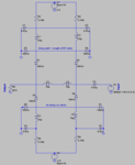
In the attached image if voltage source V1=+2.5v & V2=-2.5V, The upper section consists of Forward biased diodes, hence the signal will pass through From I/P (V3 ) to O/P Section via Delay path. The required angle of rotation is provided by delay path line.
While in Converse the signal will pass through a No delay path for no rotation.
Everything is fine but while measuring the VSWR(impedance) of I/P and O/P sections, It z very well matched from 30-120MHz(<2). Frequencies greater than 120MHz has very poor VSWR about 5. The cable used in the delay path is good quality one with good impedance matching up to 500MHz. So it seems that the problem is in circuitry components. The circuit components has the following specifications : R=2.7K Ohm, C=0.01uF, L=10uH & Diode is BA 482.
Friends let me frame the questions
1. Is it possible to steer the broad band beam exactly by same angle? (I mean whether the rotation is even throughout the band ?)
2. What are other methods employed to steer a broad band beam? (Cost effective Analog or Digital)
3. Is the schematic attached is feasible to operate over broad band? If yes please suggest the necessary modifications to components(R,L,C,diode) otherwise suggest any different schematics ?
4. Cascading the above schematic can effect the impedance matching ? If so how to tackle the coupling problem?
Sorry for my bad English:-( I'm eagerly waiting for your valuable suggestions:-D