exp
Full Member level 1
Hi,
I do not have a good feeling about IIP3 - can someone give me "typical" IIP3 values for very good, medium bad as used in high end performance (oscilloscopes) or medium (RF)?
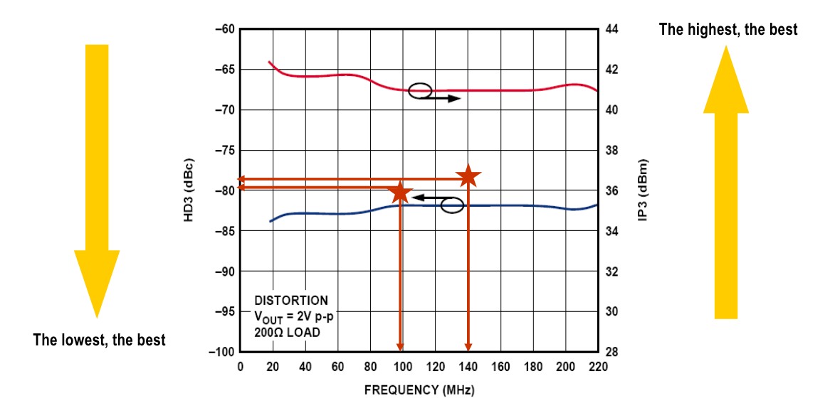
I am more used to HD3 (where I know -40dB is bad, -60dB is medium and -70 to -90 is superior).
In fact, I prefer HD3 over IIP3 because it does not allow "cheating" by just lowering the signal amplitude. What I mean is: Suppose I am interested to quantify which level of non-linearity results in which end-to-end error at system level (e.g. normalized mean squared error of a resulting signal). If I say now for a certain error level I need IIP3=x dBm I can just cheat and make it better by lowering the input signal amplitude. However, if I say I need linearity of HD3=60dB, I can not cheat because the non-linearity coefficients depend on the input amplitude. Hence
IIP3 = f(HD3,vi)
I tried to relate these two and get for example that IIP3=64.1dBm in order to get the same effect of third-order distortion for a sine wave as with HD3=-80dB at 1.24V.
Alternatively (with an amplitude 1000x smaller, i.e. 1.24mV) I get IIP3=4.1dBm.
How to I get there?
I model the non-linearity as y = c1*c + c3*x^3
From this I conclude that c3 = 4*c1/(3*Viip3^2)
Then I convert Viip3^2 to dBm assuming a resistance of 1 Ohm and a sinusoid with amplitude Viip3. Then IIP3 is given by Viip3^2/2 W which is in turn IIP3 = 10*log10(Viip3^2/2 * 1000) dBm
On the other hand, from the definition of HD3 I know that for a certain HD3, c3 must be:
c3 = 4*c1*HD3/vi^2
Equating both results and expressing IIP3 in dBm and HD3 in dB I obtain:
IIP3_dBm(HD3_dB, vi_V) = 30 - 10*log10(6) - 1/2*HD3_dB + 10*log10(vi_V^2)
While I know that HD3=-80dB is possible (although tough), does IIP3=64.1dBm for Vi=1.24V make sense (or 4.1dBm for 1.24mV)?
Thank you!
I do not have a good feeling about IIP3 - can someone give me "typical" IIP3 values for very good, medium bad as used in high end performance (oscilloscopes) or medium (RF)?
I am more used to HD3 (where I know -40dB is bad, -60dB is medium and -70 to -90 is superior).
In fact, I prefer HD3 over IIP3 because it does not allow "cheating" by just lowering the signal amplitude. What I mean is: Suppose I am interested to quantify which level of non-linearity results in which end-to-end error at system level (e.g. normalized mean squared error of a resulting signal). If I say now for a certain error level I need IIP3=x dBm I can just cheat and make it better by lowering the input signal amplitude. However, if I say I need linearity of HD3=60dB, I can not cheat because the non-linearity coefficients depend on the input amplitude. Hence
IIP3 = f(HD3,vi)
I tried to relate these two and get for example that IIP3=64.1dBm in order to get the same effect of third-order distortion for a sine wave as with HD3=-80dB at 1.24V.
Alternatively (with an amplitude 1000x smaller, i.e. 1.24mV) I get IIP3=4.1dBm.
How to I get there?
I model the non-linearity as y = c1*c + c3*x^3
From this I conclude that c3 = 4*c1/(3*Viip3^2)
Then I convert Viip3^2 to dBm assuming a resistance of 1 Ohm and a sinusoid with amplitude Viip3. Then IIP3 is given by Viip3^2/2 W which is in turn IIP3 = 10*log10(Viip3^2/2 * 1000) dBm
On the other hand, from the definition of HD3 I know that for a certain HD3, c3 must be:
c3 = 4*c1*HD3/vi^2
Equating both results and expressing IIP3 in dBm and HD3 in dB I obtain:
IIP3_dBm(HD3_dB, vi_V) = 30 - 10*log10(6) - 1/2*HD3_dB + 10*log10(vi_V^2)
While I know that HD3=-80dB is possible (although tough), does IIP3=64.1dBm for Vi=1.24V make sense (or 4.1dBm for 1.24mV)?
Thank you!