bgpavan
Junior Member level 2
Hello ,
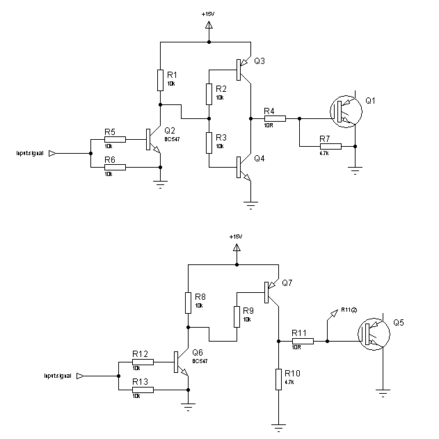
I am trying to Interface IGBT NGB8245N from ON semiconductor to an 8051 microcontroller ,My question is can i connect the output pin of the microcontroller directly to the gate of the IGBT .Will I need to have any kind of isolation cktry like opto isolator or any drive cktry to drive the IGBT .Please help
Thanks,
Regards
BG