Continue to Site

Welcome to EDAboard.com

Welcome to our site! EDAboard.com is an international Electronics Discussion Forum focused on EDA software, circuits, schematics, books, theory, papers, asic, pld, 8051, DSP, Network, RF, Analog Design, PCB, Service Manuals... and a whole lot more! To participate you need to register. Registration is free. Click here to register now.

IF amplifier design question

Status
Not open for further replies.

slimbobaggins

Newbie level 6
Joined
May 6, 2011
Messages
14
Helped
0
Reputation
0
Reaction score
0
Trophy points
1,281
Activity points
1,430
Not sure if this belongs here or in the RF section.

Looking for a little advice from Analog/ RF Engineers:

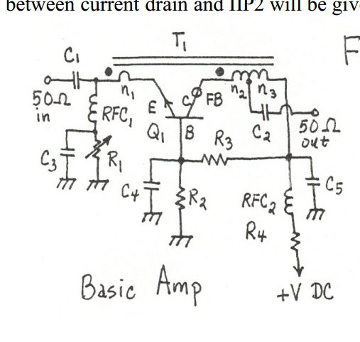
My IF coming out of my circuit is 1MHz, and I'm using approximately the following amplifier circuit to amplify it:


It's taken from this paper:
http://www.thegleam.com/ke5fx/norton/lankford.pdf

Anyhow, my transistor is a MMBT2222A (surface mount version of 2N2222A), my transformer ratio is 1:11:4, and is wound on an Amidon Multi-aperture core BN-73-2402. It gives me about 11.5 dB of gain that is fairly linear (+/- 0.1 dB) from -80 to -10 dBm input.

Above -10 dBm it starts to roll off, but not terribly, gain at +10 dBm is 3.72 dB.

My question is, what do you think my limiting factor is that's causing my gain to roll off? Am I saturating my core, or am I hitting the upper limit of my transistor? I can probably dig up some bigger cores to test with, if it's my core that's holding me back. My transistor selection is kinda limited atm, and honestly I tried the circuit with a transistor that was supposed to be much "nicer," and it didn't work as well as this does.

I should mention, my supply voltage is 12V, not 9V like in the paper. I should probably re-bias the transistor, but it worked well as-is so I didnt screw with it. Supply current is set to 24mA via the pot... Seemed to like it the best.
 
Last edited by a moderator:

I think 24 mA is fairly high to offer a better linearity. In my opinion, the neutralizing feedback is not necessary in common base amplifiers. I would try to switch it off, to remove n1 coil from the emitter. I would also try another 2N222 or another transistor to get a higher output power.
Did you try to look how amplifier linearity is affected by adjusting R1?
Please monitor the DC current to avoid burning the transistor.

- - - Updated - - -

In the original paper it is indicated that the optimum DC current is rather ~10 mA, also other transistors were used.
 

I am a little confused , why do you require a linear IF amp with + 10 dBm output?. Is this pre-IF filtering? If its post filtering then any distortion products would be a N X the IF, so should be filtered out easily. We used to build communication receivers which had i/ps of about -120 dB with a 1V input and never did anything like this. You need good linearity in the first IF (double superhet) as its before the main IF filtering, but the RF input level was controlled with an electronic attenuator.
Frank
 

I should explain the application...

RF input is 1497 MHz, level is -80 dBm to +20 dBm. There's two configurations for the receiver:

1) 4 dB conversion gain, relevant input level is -60 to +4 dBm, output signal level must not drop below 13 dBm for inputs 10 dBm and higher, noise figure <= 16 dB.

2) 30 dB conversion gain, relevant input level is -80 to -20 dBm, output signal level must not drop below 13 dBm for inputs -17 dBm and higher, noise figure <= 12 dB.

My overall circuit right now:

RF in -> lowpass filter -> gain block amp -> bandpass -> 1 dB matching attenuator -> mixer (ADL5365), mixed with 1496 Mhz -> output through 1:1 xformer and into this amplifer. The linearity of this amp is pretty good so it helps keep the noise figure reasonable across the entire circuit.

I was using the gain block amplifier up front to keep the noise figure reasonable, but unfortunately I can't find one that has a high enough input P1dB to not go non-linear on the upper end of the spectrum input. The conversion loss of the mixer is -7.5 dB... so I was thinking on giving up the input amplifier and upping the gain in the downstream amps and hoping I could meet my noise figure spec.

So... this amp is pre- IF filtering and is used to help keep the noise figure reasonable.

I built the amp is the components as described in the example, and with 9V input, found that the linearity was best at 24-25 mA, not 10 mA (this was using the MMBT2222A). I upped the supply voltage to 12V because that's whats available to me, and adjusted the current back to 24mA using R1. I did try a few different current levels at 12V by adjusting R1, but again, 24mA seemed to be the magic number.

I picked the MMBT2222A because when I built the circuit on a proto board I had a 2N2222A available to me, and I have to use a surface mount transistor.

Obviously the transistor bias at 12V is now different than it was in the initial circuit at 9V, so I'll switch the bias resistors to get the bias back to where it was, and see if that pics up linearity on the top end at all.

No one seems to think it's my core that's saturating? I'm fairly certain I have the next size up core of same material, so that could be a "silver bullet" if I'm limited by the core and not the transistor.
 

Don't you think that 10dBm or 2Vpp on emitter is driving your transistor into nonlinear regime producing harmonics on account of fundamental sine wave?
 

If RMS Load current is greater than Ic bias, then collector it will be starved for current and distorted and thus reduced gain.

Output power must be less than 24mA * 50Ω ~ 100mW peak.

Does output power increase with 100Ω load? i.e. did Impedance match work out?
 

I think an RF input of -80 -> +20 dBm, requires a power RF amp with the electronic attenuator. we used a pair of transistors in push pull running at 50 mA Ic with a 20 dB gain. I can not remember its noise factor, but the object was to reduce the dynamic range of the pre-mixer signal, say to (in your case) -60 -> -3 dB. With that sort of gain it (mainly) determines the overall NF of the receiver. You have showed us an IF amplifier with a design max signal of + 10 dBM.There is no mention of AGC to reduce the +20 dBm level signals at this point. If you use delayed AGC, the gain will remain high for low level signals and will reduce the output for high level signals, so reducing the need to handle large signals. Use forward AGC, increasing the collector current to damp the input circuits.
Frank
 
Thank you all for the responses, sorry I didn't get a chance before now to respond.

@ Borber's question about driving the transistor into a nonlinear region, the answer is I don't know? To be brutally honest, up to this point I've been a digital design guy and haven't touched a transistor prior to this since I was school, so this is a learning curve/ refresher for me.

@Sunny: I can throw a 100Ω load on and check the response. I've got that circuit on a bread board right now, and the output going into the Spec An which is 50Ω non-adjustable.

@Chuckey: First scratch of the board that we used this transistor amp on did not have any input level control; I was initially designing this for the -80 to -20 dBm input and didn't care that the amp rolled off higher up; I the decided that I wanted to just make one board for both functions, and of course now I care... hind site is 20-20. I can't really have "adjustable" gain control though, in the sense that I don't want the gain to decrease as input signal increases (as long as the signal level is in the relevant range specified). As long as the input signal is 10 dBm or higher I can limit it, but below that the gain as to be linear throughout the range.
 

Status
Not open for further replies.

Similar threads

Part and Inventory Search

Welcome to EDABoard.com

Sponsor

Back
Top