Continue to Site

Welcome to EDAboard.com

Welcome to our site! EDAboard.com is an international Electronics Discussion Forum focused on EDA software, circuits, schematics, books, theory, papers, asic, pld, 8051, DSP, Network, RF, Analog Design, PCB, Service Manuals... and a whole lot more! To participate you need to register. Registration is free. Click here to register now.

IE3D:What is the Terminating Impedance Zc?

Status
Not open for further replies.

chowlong

Newbie level 4
Joined
Dec 31, 2012
Messages
6
Helped
0
Reputation
0
Reaction score
0
Trophy points
1,281
Activity points
1,327
Hi all.

I am going to design a antenna to match the chip impedance with 22-196j.
What is the Terminating Impedance Zc i need to set?

Terminating Impedance mean load impedance when calculate S11(Gamma)?

From the equation Gamma = (Zc-Zo)/(Zc+Zo),

where Zc = load impedance = terminating impedance??
Zo = source/chip impedance

So the terminating impedance = 22-195j to achieve Gamma to zero.
Am i correct?
 

I quite don't get what you are actually asking... however as a general rule in RF we terminate with 50 ohm or 75 ohm impedance
 

Hi smoothcriminal,

Thanks for your reply and sorry about the clearness of the question.

Now i am going to design a RFID antenna and match the chip impedance which is 22-196j

In IE3D , i want to obtain the S11 graph after simulation.

What should i set in terminating impedance Zc?

I can sure it shouldn't be 50 or 70 ohm.

Should it set to 22-195J or 22+195J?

Correct me if it is wrong.

Thanks so much=)
 

ok what i understand is that you want to match the source impedance to load impedance (22-196j) and you are confused whether to use 22-196j or 22+196j as terminating impedance!!!
the ans is you use "complex conjugate" of the impedance that the load is offering .. in your case load is offering 22-196j so you will use 22+196j as terminating impedance ... and match it to source impedance... you can verify it through s11 graph !! more negative amplitude in db means less relection back!!
 

    V

    Points: 2
    Helpful Answer Positive Rating
22+195J IF you put the antenna right at the output terminal(s) of the chip. If there is a transmission line inbetween the antenna and IC, then you need to make the antenna match to a very different impedance!
 

Thanks for your reply again =)

1)I am confusing about the source impedance and load impedance.
In this case ,
source impedance = chip impedance (22-196j) ?
load impedance = antenna impedance( 22+196j) ?

And i agree with "the ans is you use "complex conjugate" of the impedance that the load is offering"

I think terminating impedance = 22-196j

Correct me if i am wrong.Thanks all.

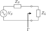
Reflection_Coefficient_Circuit.png
 

As you said (which you should have specified before)
source impedance = chip impedance (22-196j)
load impedance = antenna impedance( 22+196j)

we all know Zl=Zs* , which means if your load is equal to complex conjugate of your source, which is in your case as you say source is (22-196j) and load is (22+196j) then max power will travel...
 

This is my summarize.Am i right about the understanding of terminating impedance?

Given: chip impedance = 22-196j

Below is my approach,

Step1) design a pattern on patch antenna to obtain a Z-parameter graph

which (ideal case : antenna impedance = 22+ 195j between 860 to 940MHz)

Step2) input terminating impedance to calculate S11

reflection coefficient = (Zload - Zsource)/(Zload + Zsource) < -10db

( circuit diagram is attached)Reflection_Coefficient_Circuit.png

Zload = antenna impedance (22+195j)

Zsource = chip impedance (22-195)

terminating impedance is the "complex conjugate" of the impedance that the load is offering

So terminating impedance = 22-195j


Thanks.
 

Status
Not open for further replies.

Similar threads

Part and Inventory Search

Welcome to EDABoard.com

Sponsor

Back
Top