Continue to Site

Welcome to EDAboard.com

Welcome to our site! EDAboard.com is an international Electronics Discussion Forum focused on EDA software, circuits, schematics, books, theory, papers, asic, pld, 8051, DSP, Network, RF, Analog Design, PCB, Service Manuals... and a whole lot more! To participate you need to register. Registration is free. Click here to register now.

[SOLVED] ideal opamp for integrator

Status
Not open for further replies.

vaah

Member level 3
Member level 3
Joined
May 24, 2012
Messages
67
Helped
1
Reputation
2
Reaction score
1
Trophy points
1,288
Location
US
Activity points
1,785
Hello,

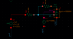
I would like to build an ideal integrator in Cadence. Currently, I am using "VCVS" as an amplifier shown in the fig opamp_cap.PNG

When I simulate the circuit, apparently, capacitor feedback does not work properly. The opamp model acts like a comparator. As long as negative input has a larger voltage output shows the minimum voltage and Vice versa. I am wondering if someone might have the same problem. I appreciate it if you could let me know how to resolve the issue!

Do you have any suggestion how to model an ideal integrator in Cadence? Preferably, I do not want to use Verilog-A opamp.

Thanks.
 

Attachments

  • opamp_res_feedback.PNG
    opamp_res_feedback.PNG
    10.2 KB · Views: 240

crutschow

Advanced Member level 6
Joined
Feb 22, 2012
Messages
4,316
Helped
981
Reputation
1,960
Reaction score
1,062
Trophy points
1,393
Location
Colorado USA Zulu -7
Activity points
24,429
Your integrator time constant is only 50nS.
Is that what you wanted?
Try a larger integration capacitor.
 

vaah

Member level 3
Member level 3
Joined
May 24, 2012
Messages
67
Helped
1
Reputation
2
Reaction score
1
Trophy points
1,288
Location
US
Activity points
1,785
Your integrator time constant is only 50nS.
Is that what you wanted?
Try a larger integration capacitor.

Thank you
I have tried to use a larger capacitor but I still have the issue.
 

FvM

Super Moderator
Staff member
Advanced Member level 7
Joined
Jan 22, 2008
Messages
51,214
Helped
14,651
Reputation
29,580
Reaction score
13,795
Trophy points
1,393
Location
Bochum, Germany
Activity points
292,737
When I simulate the circuit, apparently, capacitor feedback does not work properly. The opamp model acts like a comparator. As long as negative input has a larger voltage output shows the minimum voltage and Vice versa.
That's how an integrator is expected to work. Sounds like you didn't yet think about a reasonable test setup for your integrator.

It can go like this:
Apply an initial condition that holds the integrator capacitor discharged, and watch the output signal starting from this point.

In a real circuit, an integrator would either us a reset switch or external negative feedback.
 

vaah

Member level 3
Member level 3
Joined
May 24, 2012
Messages
67
Helped
1
Reputation
2
Reaction score
1
Trophy points
1,288
Location
US
Activity points
1,785
That's how an integrator is expected to work. Sounds like you didn't yet think about a reasonable test setup for your integrator.

It can go like this:
Apply an initial condition that holds the integrator capacitor discharged, and watch the output signal starting from this point.

In a real circuit, an integrator would either us a reset switch or external negative feedback.

Thank you FvM,
Yes you are right! This is how an integrator is expected to work.

I had applied some initial condition to some nodes and also as you can see from the uploaded photo, ive added a resistor in parallel with the capacitor to make sure about the feedback!

What do you mean about a reasonable test setup? Can you please tell me specifically?
Thanks.
 

LvW

Advanced Member level 6
Joined
May 7, 2008
Messages
5,869
Helped
1,750
Reputation
3,506
Reaction score
1,354
Trophy points
1,393
Location
Germany
Activity points
39,946
each opamp suffers from input offset which produces an unwanted dc output. In case of pure capacitive feedback this dc voltage causes an unwanted charging of the capacitor.
Hence, dc (resistive) feedback is required in form of a resistor parallel to the feedback capacitor.
However, this resistor disturbs the integration.
As a consequence a trade-off is necessary (as very often ikn analog electronics):
The feedback resistor should be as large as possible (regarding its influence on the integration process) and as small as necessary (with regard to its dc stabilization task).
 

vaah

Member level 3
Member level 3
Joined
May 24, 2012
Messages
67
Helped
1
Reputation
2
Reaction score
1
Trophy points
1,288
Location
US
Activity points
1,785
each opamp suffers from input offset which produces an unwanted dc output. In case of pure capacitive feedback this dc voltage causes an unwanted charging of the capacitor.
Hence, dc (resistive) feedback is required in form of a resistor parallel to the feedback capacitor.
However, this resistor disturbs the integration.
As a consequence a trade-off is necessary (as very often ikn analog electronics):
The feedback resistor should be as large as possible (regarding its influence on the integration process) and as small as necessary (with regard to its dc stabilization task).

Thank you

exactly! But I have applied a saw waveform and also applied initial condition. Theoritacclly, i think the circuit shold work, shouln't it?
 

FvM

Super Moderator
Staff member
Advanced Member level 7
Joined
Jan 22, 2008
Messages
51,214
Helped
14,651
Reputation
29,580
Reaction score
13,795
Trophy points
1,393
Location
Bochum, Germany
Activity points
292,737
You didn't show any waveforms so we can't know if your test setup is correct.
 

vaah

Member level 3
Member level 3
Joined
May 24, 2012
Messages
67
Helped
1
Reputation
2
Reaction score
1
Trophy points
1,288
Location
US
Activity points
1,785
You didn't show any waveforms so we can't know if your test setup is correct.

Right, please take a look at the photo.
Waveform.jpg

the amplifier has 4 pin, Vi+ Vi- Out and (Vg connected to ground). I have applied a DC voltage to Vi+ and I have a negative feedback for the amplifier. The problem is, as I told earlier, the capacitive feedback doesn't work, however I put a large resistor in parallel with the capacitor.

I have also tried to make a switched-cap with an ideal amplifier. See the photo. I assumed that the amplifier works properly. But unfortunately, I have more problem with this circuit.
Circuit.PNG
 

D.A.(Tony)Stewart

Advanced Member level 7
Joined
Sep 26, 2007
Messages
7,240
Helped
1,742
Reputation
3,483
Reaction score
1,779
Trophy points
1,413
Location
Richmond Hill, ON, Canada
Activity points
52,730
10 pF Cap will integrate and saturate in microseconds. Remember dv/dt=I/C so with C=1e-11 the slewrate is far too fast.
Try 1 nF. or calculate what you need.
 

vaah

Member level 3
Member level 3
Joined
May 24, 2012
Messages
67
Helped
1
Reputation
2
Reaction score
1
Trophy points
1,288
Location
US
Activity points
1,785
10 pF Cap will integrate and saturate in microseconds. Remember dv/dt=I/C so with C=1e-11 the slewrate is far too fast.
Try 1 nF. or calculate what you need.

Thank you.
You are right I should consider the charge and discharge timing. I am using a triangle and saw waveform. So incited of using large value for capacitor, I change the frequency of input.

BTW, it seems my circuit works. If it helps to others:
I couldn't simulate an integrator. However, when I added some switches to the circuit it works. The other problem for "vsvs", a component in analogLib" was "time delay".

Also, be careful for your simulation setting, specifically, "gmin". dont float a node, put a large resistor!

Thank you all!
 

Status
Not open for further replies.

Similar threads

Part and Inventory Search

Welcome to EDABoard.com

Sponsor

Top