Vermes
Advanced Member level 4
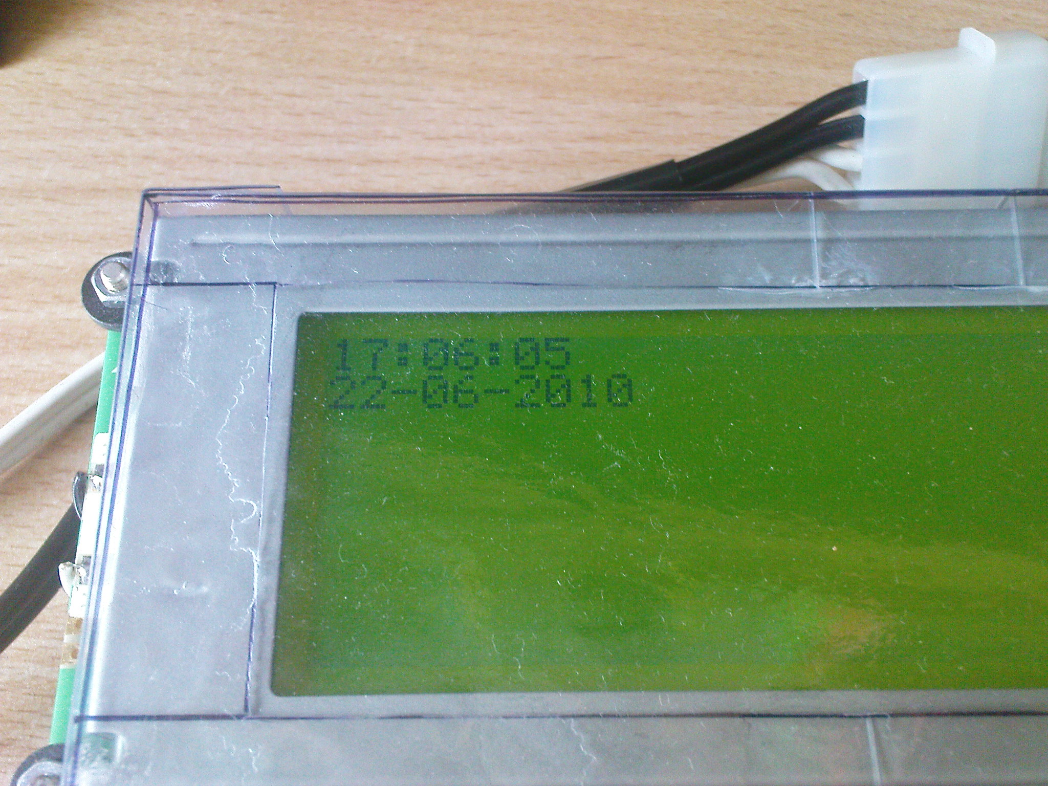
It is an useful device for everyone who does not want to set the clocks of systems with RTC each time after disconnecting the power. This clock module with battery back-up is made on a universal board.
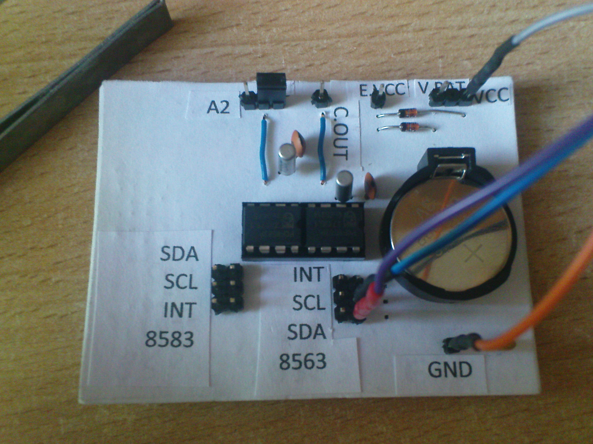
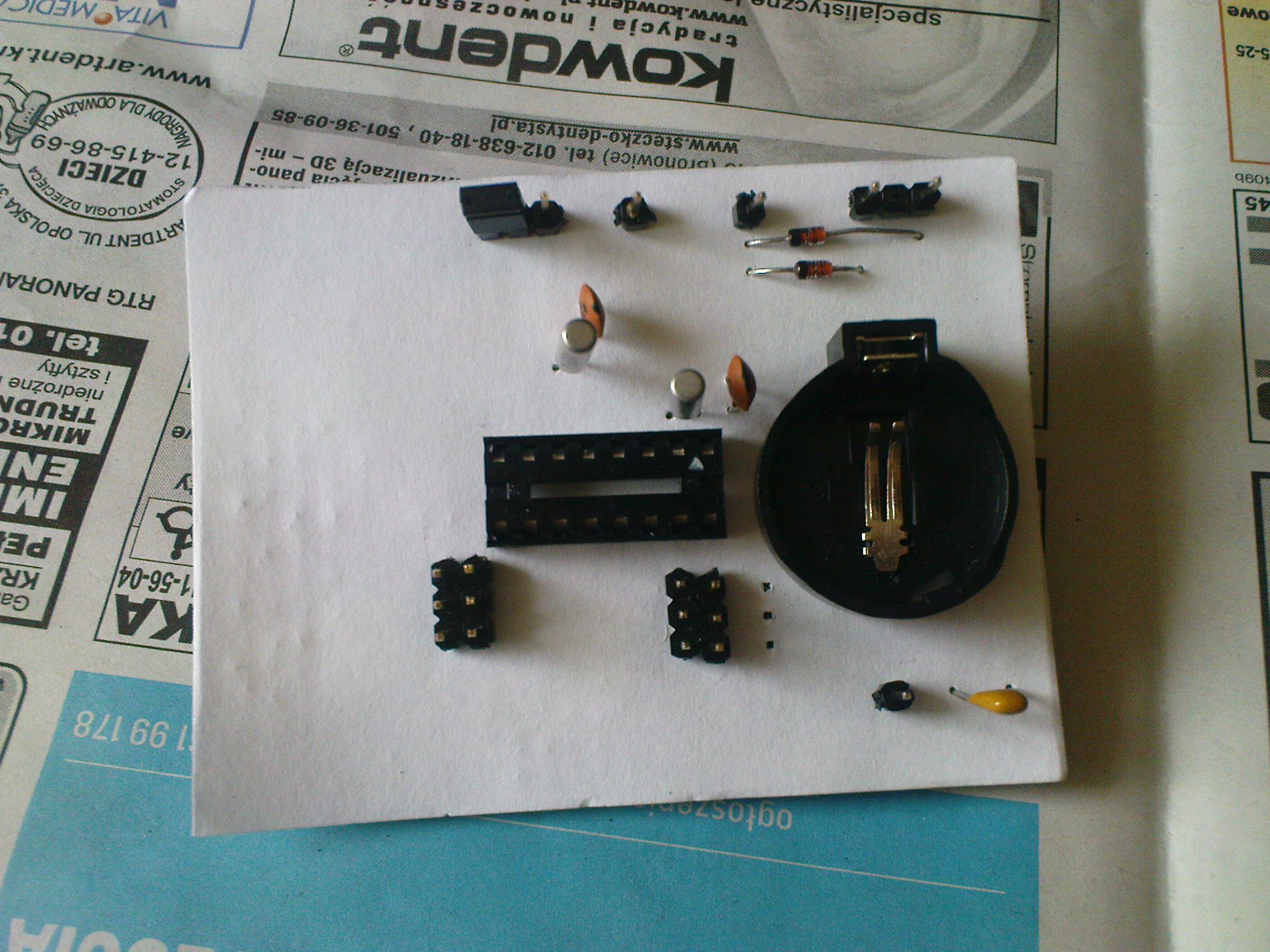
Elements of the PCB:
- PCF8563 with contacts: I2C (SDA+SCL), INT and CLKOUT and permanently connected resonator
- PCF8583 with contacts: I2C (SDA+SCL), INT and a possibility to change the system address (by default it is A0(hex), it can be changed to A2 and A3) using a jumper and connected resonator
- 3V battery with diodes preventing from „charging” the battery when normal supply is on and locking powering the rest of the system when the supply is off
In addition there is a supply pin which allows you to connect other system to the battery back-up and a pin directly connected to the battery, which allows control of the battery voltage by processor and indication when it needs to be replaced.
Additional function is possibility to connect only SDA, SCL and GND lines. Then the systems are powered from a battery and operate normally.
Pictures:
Link to original thread - Moduł zegarowy I2C z PCF8563 i PCF8583