Continue to Site

Welcome to EDAboard.com

Welcome to our site! EDAboard.com is an international Electronics Discussion Forum focused on EDA software, circuits, schematics, books, theory, papers, asic, pld, 8051, DSP, Network, RF, Analog Design, PCB, Service Manuals... and a whole lot more! To participate you need to register. Registration is free. Click here to register now.

I need help with the instrumentation amplifier

Status
Not open for further replies.

antonydublin

Newbie level 5
Joined
Aug 15, 2011
Messages
10
Helped
0
Reputation
0
Reaction score
0
Trophy points
1,281
Activity points
1,364
Hello everyone. Sorry for my bad English.
I need some help with the instrumentation amplifier.
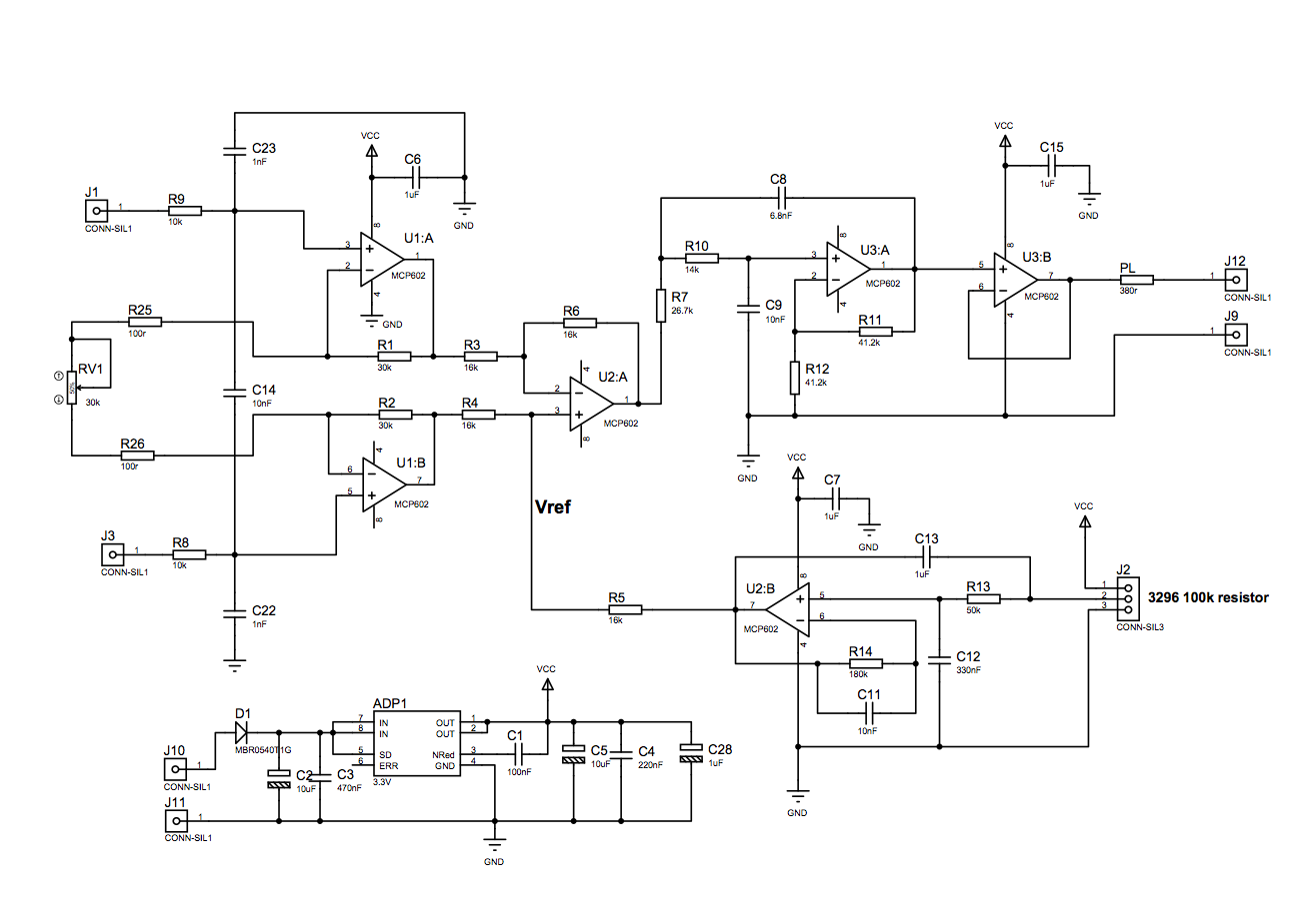
Look at the analog part of my scheme below.
I'm using 3-OpAmp scheme on MCP602 operational amplifiers (U1:A, U1:B, U2:A), filtered reference (U2:B), active filter
(U3:A), single supply on ADP3303 - 3.3V, 1% resistors. But independently from value of the potentiometer RV1 gaine
is always near "2". I have tried different reference voltage and other amplifiers. The same result on the breadboard and
board. What is wrong?

P.S. I understand that the discrete design for the instrumentation amplifier are not greet in our days,
and it is better to use something like AD620 or AD8220 , but this scheme is cheaper in terms of repair.
View attachment MCP_InAmp.pdf
 
Last edited:

Sorry, the attachement cannot be opened.
 

Sorry, the attachement cannot be opened.
@LvW: It's a simple PDF. Here's the corresponding PNG image:
 
  • Like
Reactions: LvW

    LvW

    Points: 2
    Helpful Answer Positive Rating
What is wrong?
Apparently your real circuit isn't corresponding to the shown schematic. Or the input voltage isn't within the common mode range of MCP602.
 

@LvW: It's a simple PDF. Here's the corresponding PNG image:

Thank you erik. However, the original link from antonydublin was not pdf. Now, he has changed the format.
 

Thanks, FvM.
I'm already made a PCB (only with smd 1206 components), it checks with scheme, so my circuit is correct. There is also a digital part, that works fine. Also grounding is correct. But anyway, I do not expect that amplifier will not work. After all I use the prototyping board with MCP602 in DIP - the same result. MCP6002 - the same. About common mode range. To test circuits I used different sources from 1mV to 3V (high/low impedance), always higher then ground.
 

Antonydublin, what is the output dc voltage of U2-B (reference supply) in terms of Vdd?
 

Output voltage of U2:B is 1.65V. The output of U2:A in this case 1.65 (when inputs of U1:A/B are connected together).
When signal occurs on inputs of U1:A/B the output changes U2:A like 1.65+"2"*(V1-V2). This means that the differential part work correct, it seams that input amplifiers U1:A/B are not working, and gives only input buffering, something like that.
Also I try to set R5 to ground. Output of U2:A close to ground - 1.5 mV when inputs of U1:A/B the same potential.
Today I'll try to use LM358 instead of MCP6XX.
 

Sounds like a wiring error (open circuit R25/R26/RV1) or shorted R1/R2. MCP602, although somewhat noisy, should be basically fine. Common mode range is very similar to LM35, means no input rail-to-rail, input range about 0 to 2V with 3.3V supply.
 

I'm looking at breadboard right now. Wirings correct. I change resistor values. Nothing.
Some mysticism.
 

Output voltage of U2:B is 1.65V. The output of U2:A in this case 1.65 (when inputs of U1:A/B are connected together).
When signal occurs on inputs of U1:A/B the output changes U2:A like 1.65+"2"*(V1-V2). This means that the differential part work correct, it seams that input amplifiers U1:A/B are not working, and gives only input buffering, something like that.
Also I try to set R5 to ground. Output of U2:A close to ground - 1.5 mV when inputs of U1:A/B the same potential.
Today I'll try to use LM358 instead of MCP6XX.

Antony, are you aware that in this case the dc output (operational point) of U3:A (filter stage) is 1.65*2=3.3 volts ?
 

I've test it without filter stage.
In fact, filter gain in circuit equal to 1 (instead putting R12 to the ground I left it sealed off, R11 = 0r).
Thanks for your replies. I made some replacement today: instead of U1:A/B, U2:A I use AD623.
It works fine.
 

Status
Not open for further replies.

Similar threads

Part and Inventory Search

Welcome to EDABoard.com

Sponsor

Back
Top