Continue to Site

Welcome to EDAboard.com

Welcome to our site! EDAboard.com is an international Electronics Discussion Forum focused on EDA software, circuits, schematics, books, theory, papers, asic, pld, 8051, DSP, Network, RF, Analog Design, PCB, Service Manuals... and a whole lot more! To participate you need to register. Registration is free. Click here to register now.

I need help in designing an IR emitter and sensor circuit with ANALOG VOLTAGE OUTPUT

Status
Not open for further replies.

maxima_diesel

Junior Member level 1
Joined
Feb 15, 2012
Messages
19
Helped
0
Reputation
0
Reaction score
0
Trophy points
1,281
Activity points
1,463
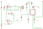
Hi, Im a student and we have a project where we are designing a touchless air piano (similar effect to this: A New Instrument - how it works - YouTube). I am in charge in designing the sensors. Basically the sensors would have to detect the distance of the hand from the sensor. The output should be analog in between 0 to 5V, this output is connected to an ADC to be interpreted. The distance of the hand to the sensor is needed for velocity calculation. So basically the close the hand gets to the sensor the louder the air piano's key would get. I have done some research prior to this post but a little assistance would help a lot from you guys. I have tested modulated sensors with different carrier frequencies and I used 555 timer to set the output of the emitter to the correct frequency. The only problem is that, modulated sensors like that I have used like this : http://www.rentron.com/Files/pna4601m.pdf An issue with this sensor is that the output that it generates is digital-ish, meaning when it senses an object (hand) it turns to 4.8v and when its not sensing anything its at 700mv. It isn't analog at all, It's liek there's a threshold, the only advantage of this is that its already modulated and the range is approximately 30 cm. However, I have found a sensor similar to this but the output voltage doesnt vary with distance rather with the pulse width, and when I looked at the output from the oscilloscope it seems that it still had a threshold voltage when the hand is detected, not good enough. My aim is basically create an IR sensor and receiver with an output similar to this well-known ready made sensor that everyone uses: http://www.farnell.com/datasheets/653395.pdf or SHARP|GP2Y0A02YK0F|SENSOR, DISTANCE, ANALOGUE O/P | Farnell United Kingdom. The pre-made sensors have a real analogue output which is what we needed because velocity calculation would be possible and it is our aim for our project. Then I tried creating another ir emitter sensor circuit with ANALOG voltage output. I strated by basically creating the circuit stated in this tutorial: **broken link removed**. Instead of using a 3-pin modulated sensor I just used a basic IR LED receiver (2 pins) and IR LED emitter, just like it says in the tutorial. The output voltage of this setup is analog indeed but, the range it has is only 4.7V to 5.0V. The range is 300mV, which is not enough. I need an analog output voltage from 0 to 5 V. So I decided to connect the output of the IR sensor to a BJT like in this setup: **broken link removed**. I've to modify that circuit because the IR emitter is not connected to a microcontroller in my design, and the analog output is not connected to a microcontroller either. With this setup output is definitely analog but the range is 3V to 5V, but I need an analog output to be 0 to 5V or even 0 to 3V. I am thinking of connecting the output of this setup to an op amp to convert the range to 0 to 5v, but I am not sure how to, is it ok if any of you guys can assist me on doing this? The range of this setup is 25-30cm which is good enough. Also I would like to know how to modulate the IR LED sensor so that it will become more immune to ambient lighting, I think I could use a bandpass filter maybe?? Basically again my aim is to have analog output voltage from 0 to 5V, immune to ambient lighting, range should reach approximately 30cm. I would greatly appreciate any of your assistance. Thank you very much in advance.
 

I have not gotten into the Sharp sensors; although, I have seen a number of projects based on them. I don't know if they can be modulated in addition to what may already be present to avoid extraneous IR.

Vishay also makes an analog sensor you may want to look at: **broken link removed**

Finally, since this project just seems to be just beginning, there is another sensor called a capaciflector that you may want to consider:

Projects - Dexterous Manipulation Laboratory

Unfortunately, that site has changed a bit since I made one several years ago and some of the earlier links seem to be missing. Basically, the work was sponsored by NASA for robotics. It is a directional capacitance sensor for distance. One interesting use was guide a robot to examine the interior of a rocket engine without bumping into the sides. I downloaded a large final report from a student team that made a working robot model. It and its appendix are a bit over 3 MB. A search for the term may return better and more recent results. If that fails, I will try to send it to you by other means. That was in the days before I saved all links. The title of the report was, "Capaciflector-Based Tracking of a Wire for Lunar Exploration (NASA Goddard Space Flight Center)," which may help you find it.

John
 

That's a ****** difficult paragraph to read!

Keith.

really sory for a long paragraph, just wanted to show that I've done some research of my own before posting a question here. thanks for the reply

---------- Post added at 09:28 ---------- Previous post was at 09:27 ----------

[/COLOR]
I have not gotten into the Sharp sensors; although, I have seen a number of projects based on them. I don't know if they can be modulated in addition to what may already be present to avoid extraneous IR.

Vishay also makes an analog sensor you may want to look at: **broken link removed**

Finally, since this project just seems to be just beginning, there is another sensor called a capaciflector that you may want to consider:

Projects - Dexterous Manipulation Laboratory

Unfortunately, that site has changed a bit since I made one several years ago and some of the earlier links seem to be missing. Basically, the work was sponsored by NASA for robotics. It is a directional capacitance sensor for distance. One interesting use was guide a robot to examine the interior of a rocket engine without bumping into the sides. I downloaded a large final report from a student team that made a working robot model. It and its appendix are a bit over 3 MB. A search for the term may return better and more recent results. If that fails, I will try to send it to you by other means. That was in the days before I saved all links. The title of the report was, "Capaciflector-Based Tracking of a Wire for Lunar Exploration (NASA Goddard Space Flight Center)," which may help you find it.

John

first of all, thanks a lot for reply, I have tried the Vishay sensors, but the output of those sensors isn't truly analog. I don't think it is suitable for what I need. The Capaciflector, does the distance of the object have a linear output with voltage? and will it have an analog voltage output?, Can you help me in trying to convert the voltage output of the 2nd system I made from 3-5v, to 0-5v? Just some guidance would be greatly appreciated. Thanks a lot again.
 

The are definitely analog. Linear no, nor do I see that as a particular disadvantage. However, you can play a tune easily with them. Just use a voltage controlled oscillator or the capacitance itself can be the tuner for an oscillator. The note will be determined by the distance of your hand from the sensor. It is not hard to imagine a piano where each key is a differently tuned capacitative sensor. The capaciflector design simply extends and focuses the range for detection.

I did my experiments in 2005-2006 and have not searched on the subject since. I settled on a different sensor, but my purpose was quite different that what you are trying to do. See what's out there. If you can't find it, we can find a way to get the information to you. I just hate to upload such large files here, if they are unlikely to be of use.

John

Edit: Here is one circuit I used. The LM567 is a tone detector. You can tune to anything you want.

attachment.php
 

Attachments

  • Capaciflector.png
    Capaciflector.png
    11.9 KB · Views: 137
Last edited:

The are definitely analog. Linear no, nor do I see that as a particular disadvantage. However, you can play a tune easily with them. Just use a voltage controlled oscillator or the capacitance itself can be the tuner for an oscillator. The note will be determined by the distance of your hand from the sensor. It is not hard to imagine a piano where each key is a differently tuned capacitative sensor. The capaciflector design simply extends and focuses the range for detection.

I did my experiments in 2005-2006 and have not searched on the subject since. I settled on a different sensor, but my purpose was quite different that what you are trying to do. See what's out there. If you can't find it, we can find a way to get the information to you. I just hate to upload such large files here, if they are unlikely to be of use.

John

Edit: Here is one circuit I used. The LM567 is a tone detector. You can tune to anything you want.

attachment.php

Thanks for the reply again John,
I have decided just to use the setup I have stated on my post where the IR transmitter and receiever circuit is connected to a BJT to increase the voltage difference and have an analog output. I may consider the capaciflector approach, but because I've already got the parts for the IR transmitter and receiver I might just try and use that for the time being. My only issue atm now is how would i convert the output voltage to analog from 0V to 5V, atm the output I am getting is 3V to 5V. I think I would need to use a non-inverting op amp but I am not too sure what value of components to use and reference voltages etc.. I have tried making the calculations to work out the values of the components, but I keep on getting negative value for resistors. All i need is an analog voltage output ranging from 0V to 5V. thanks again for your reply.
 

Status
Not open for further replies.

Part and Inventory Search

Welcome to EDABoard.com

Sponsor

Back
Top