Continue to Site

Welcome to EDAboard.com

Welcome to our site! EDAboard.com is an international Electronics Discussion Forum focused on EDA software, circuits, schematics, books, theory, papers, asic, pld, 8051, DSP, Network, RF, Analog Design, PCB, Service Manuals... and a whole lot more! To participate you need to register. Registration is free. Click here to register now.

I have 2 Questions Ac bridge and Op Amp

Status
Not open for further replies.

c110

Newbie level 3
Joined
Apr 20, 2014
Messages
3
Helped
0
Reputation
0
Reaction score
0
Trophy points
1
Activity points
22
Hi

I need the ideal solution for

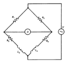
1. 20-04-2014 08-46-57 م.png

The ac bridge of figure nulls with R1= 1kohm
R2 = 2kohm , R3 = 100 ohm , L3 = 250 mH .
a-find value of R4 and L4
b.if circuit excited by 5-v,1 Khz oscillator , find the offset voltage for L4 = 510 mH.
c.what are the amplitudes of in-phase and quadrature(90 degree) components of offset voltage ?

2.A sensor varies from 1 : 5 kohm , use this in an op Amp circuit to provide voltage varying from 0 to 8 v as the resistance changes .

really I need help
Thank you very much
 

Show us what you have done so far, and tell us which part you are having trouble with (Hint start by reasoning about the bridge with DC excitation, so the inductors can be ignored the answer drops right out from examination).

We will help, but hopefully not just answer your homework problem.

Regards, Dan.
 

Mr Dan Mills ,

Thank you

In first question , Z1.Z2=Z3.Z4 and Z = R + jwl and I calculated R4 and L4 .
The problem in b and c .. when excited ac bridge by 5v , should I put R5 ? 1kohm .. and where
And the voltage components QandI from Sin over cos of Tan im over real ??

The second question , I can draw inverting op Amp and Non inverting but Should I calculate v from 0 : 8 , I mean .. v at 0,1,2,3,4,5,6,7,8 ????
 

The second question , I can draw inverting op Amp and Non inverting but Should I calculate v from 0 : 8 , I mean .. v at 0,1,2,3,4,5,6,7,8 ????

In any case, you should select an amplifier topology that has the largest input resistance (in order not to load the bridge).
 
  • Like
Reactions: c110

    c110

    Points: 2
    Helpful Answer Positive Rating
For part B, you have R4 = 200 ohms from part 1?

So Z4 = 200+jwl, easily solved with l = 510mH, w = 6.28e3
Z3 = 100 +jwl with l being 250mH in this case.

Now form two potential dividers Z3/(Z3+R1) and Z4/(Z4+R2)
The offset voltage is simply 5 * ((Z3/(Z3+R1)) - (Z4/(Z4+R2))).

Now the answer will be a voltage phasor in the complex plane, something of the form a+jb volts, the in phase component is simply a volts and the quadrature component is simply b volts, the unit vector ~j being at rightangles the the natural numbers, no need for trig here unless you did the algenbra in polar coordinates.

I leave the algebra to you.
Note that you will need to label which side of the bridge is positive to make the answer complete.

Regards, Dan.

BTW The easy way yo analyse that bridge in balance is to imagine applying DC where it becomes obvious that as R2 is twice R1, R4 must be twice R3, the same reasoning them applies to the inductors to keep the ratios the same.

Regards, Dan.

Thank you very much master ... I get it now .
What s ur opinion .. second problem ?
 

Status
Not open for further replies.

Similar threads

Part and Inventory Search

Welcome to EDABoard.com

Sponsor

Back
Top