Welcome to our site! EDAboard.com is an international Electronics Discussion Forum focused on EDA software, circuits, schematics, books, theory, papers, asic, pld, 8051, DSP, Network, RF, Analog Design, PCB, Service Manuals... and a whole lot more! To participate you need to register. Registration is free. Click here to register now.
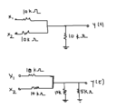
Your circuit is linear so you can calculate output for x1 and x2 separately(i mean, output y1 for x1, x2 is grounded; y2 for x2, x1 grounded), then y=y1+y2. So for the first image y(t)=1/3(x1(t)+x2(t)). For the second, y(t)=1/5(x1(t)+x2(t)).
Reards.
thanks for the reply. so when we add two signals with different frequencies we just leave the equations as is ? like cos (at)+cos(bt) ? also, when the frequencies are the same like acos (at) and bcos (at) then what would be the case ?
Hi
you just find transfer function from input to output for each signal, assuming all other = 0 (i. e. grounded). This transfer function may depend on signal frequency if you for example have frequency-dependent components in your network (but it's not your case). After doing all this, the overall output will be y(t)= TF1*x1(t)+TF2*y2(t)+.... The key point here is that for linear network you can calculate response for each input separately and then add them. Hope my explanation is clear.
Regards.
This site uses cookies to help personalise content, tailor your experience and to keep you logged in if you register.
By continuing to use this site, you are consenting to our use of cookies.