Continue to Site

Welcome to EDAboard.com

Welcome to our site! EDAboard.com is an international Electronics Discussion Forum focused on EDA software, circuits, schematics, books, theory, papers, asic, pld, 8051, DSP, Network, RF, Analog Design, PCB, Service Manuals... and a whole lot more! To participate you need to register. Registration is free. Click here to register now.

How to use pic microcontrollers?

Status
Not open for further replies.

rado

Member level 2
Member level 2
Joined
Feb 15, 2014
Messages
42
Helped
1
Reputation
2
Reaction score
1
Trophy points
8
Visit site
Activity points
293
I am a beginner using PIC microcontrollers , what should you care about while using a pic microcontroller?
i had programmed it, done the whole circuit on a breadboard. the board was somewhat crowded. and the response was not good. so i decided to start the same part by part.
I am using an 8MHz crystal oscillator, gives a 5v supply.
how should i check the response of microcontroller?
how much voltage should i expect at the output ports?
should i use a resistor to connect the clear pin to 5v supply?
shall i connect the output directly to a 7447 ic chip {BCD to 7 segment decoder }?
I expects your advice, instructions etc;-)
 

how to test the output voltage of pic?
after connecting the crystal oscillator, clear pin to high 4.8v , VSS to ground,VDD to +4.8v,
yet no response from the programmed pic why?
 

Re: using pic microcontrollers

MCLR pin should be connected to +5V through a 10k resistor. VSS to GND and VDD to +5V. There should be a 100 nF Ceramic between VDD and VSS pins close to PIC. Crystal and its 27 pF Ceramic Capacitors should be close to PIC.
 

Re: using pic microcontrollers

Hi,

It would help if you said which Pic chip you are using ?

You should see over +4.2v on the output pins if they have been selected as an output and turned high continuously.

Ensure your 8mhz crystal and 2 caps are close to the Pics pins and secure, their fine wires can sometimes give a poor connection so the Pic will not run.
Better if you solder those 3 parts together and fit 3 thicker wires to give a sound connection into the breadbord.


Also post your program code so we can make sure that is ok.
 

Re: using pic microcontrollers

hi wp100,
Iam using pic16F877A
I am using micro c ,and the code is,

Code:
void main() {
int i,j,k;
TRISB =0;
TRISD =0;
TRISC =0;
PORTC =0;
if(PORTC.F5==1) goto check
else portc.f5 =1;
for(i=5;i>=0;i--)
{
PORTB =i;
 for(j=9;j>0;j--)
{
PORTD =j;
delay_ms(80);
}
PORTD =0;
delay_ms(80);
}
PORTD.F6  =1;
  check: PWM1_Init(1000);
PWM1_start();
PWM1_Set_Duty(125);
if (PORTB.F0==0)
{ repeat:PORTB.F4 = 1; //Run motor in clockwise
 }

 delay_ms(170);
 PORTB.F4 = 0;
 TRISB.F6 = 1;
 if(PORTB.F6==1)
  {
 PORTB.F5 = 1; //Run motor in anti-clockwise
 delay_ms(170);
 PORTB.F5 = 0;
 delay_ms(500);
 goto repeat;
  }
  else PORTD.F7=1;
  if(PORTD.F7 =1)
  {PORTD.F6 = 0;
  }
  portc.f5 =0;
   }
 

Re: using pic microcontrollers

If your hardware is not responding, first try with single LED blinking program that will help you to clear out 75% of doubts

How about configuration word
 

Re: using pic microcontrollers

Also be careful with the use of 'goto' in your program. It is a dangerous instruction if not used wisely and it's use is discouraged. You can easily jump in and out of functions without regard to nesting and cause all kinds of problems. It is beter to structure your program to avoid its use.

Brian.
 

Re: using pic microcontrollers

Hi,

The other guys will help you with the C code, but to prove your hardware you can use this .hex code which flashes all of PortB on and off every couple of seconds.

As said earlier, Pin1 should be tied to VDD via a restistor, around 10k, and ensure that both the VDD + pins 11 / 32 , and both VSS - pins 12 / 31 are connected .

If you put your volt meter on a PortB pin you will see a clear 0 to 5v swing as the port turns on and off.

You have not posted any circuit, but have you realized you can use software to decode to seven segments, so saving having to use a 7447 chip.
Each Pic output pin can drive a led up to 25ma ( maximum though the whole pic chip of around 250ma)
 

Attachments

  • flashB.zip
    229 bytes · Views: 92

Re: using pic microcontrollers

hi friends,
when i connected my motor part alone, then there is a high=+4.5v going to both the input pins of dc motor from L293D IC
My pics output is 0.2v, for both pins configured as motor drive pins.when i directly give a ground to any of these pics output pins the motor runs. did it mean that there is no perfect low/ground potential at these pins?
any idea?
 

Re: using pic microcontrollers

i used these code simply to make the port b outputs high

Code:
void main() {
TRISB= 0;
PORTB = 0xFF;
}

iam using 8MHz crystal along with 27pf capacitors
mclr is connected to 5v through 10k
but all pins show 0.08v why?
 

Re: using pic microcontrollers

Assuming you have it wired correctly, the most likely reasons are the crystal oscillator isn't running or the watchdog timer is causing rapid resettting.

Make sure you have the watchdog disabled and the oscillator is set to HS mode.

Brian.
 

Re: using pic microcontrollers

sir,I loaded your program in PIC16F877A , connected an 8MHz crystal along with 27Pf
also connected the mclr pin to+5 v through a 10k resistor. but i gets only an output voltage of .05 to .1 v
 

Re: using pic microcontrollers

Post your configuration word
 

Re: How to use pic microcontrollers

device : P16F877a
frequency: 8 MHz
Build type : release
Debugger: software
oscillator selection : HS
Watch dog timer: disabled
Power on timer: disabled
Brownout reset: enabled
low voltage in circuit serial program : disabled
Data EEPROM memory code protection: disabled
Flash program memory write: disabled
in circuit debugger: disabled
flash program memory code protection : disabled
 

Re: How to use pic microcontrollers

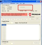
Hoped, you are programming using PICkit2 software

if yes

After you imported the HEX file to PICkit2 Software, What is the value is showing under configuration word of PICkit2 S/W

cry.JPG
 
Last edited:

Re: How to use pic microcontrollers

sir , Iam using micro c pro for pic
 

Re: How to use pic microcontrollers

Try this code and see if it works.


Code C - [expand]
1
2
3
4
5
6
7
8
9
10
void main() {
 
     TRISB = 0x00;
     PORTB = 0x00;
 
     while(1) {
             PORTB = ~PORTB;
             Delay_ms(1000);
     }    
}


Re: How to use pic microcontrollers

my guide said that it may due to, the crystal may not work properly. so advised me to test it with a CRO . should i directly connect the CRO probes to crystal?
what is the use of pullup and pull down resistor?
 

Re: How to use pic microcontrollers

what the data protection and code protection in the configuration word mean?
also what is ID1 ID2 ?
when programming, these are shown.
 

Status
Not open for further replies.

Part and Inventory Search

Welcome to EDABoard.com

Sponsor

Back
Top