Continue to Site

Welcome to EDAboard.com

Welcome to our site! EDAboard.com is an international Electronics Discussion Forum focused on EDA software, circuits, schematics, books, theory, papers, asic, pld, 8051, DSP, Network, RF, Analog Design, PCB, Service Manuals... and a whole lot more! To participate you need to register. Registration is free. Click here to register now.

How to use free running timer for Capture module.

Status
Not open for further replies.

dhakeparag81

Full Member level 2
Full Member level 2
Joined
Jun 6, 2012
Messages
142
Helped
1
Reputation
2
Reaction score
1
Trophy points
1,298
Location
INDIA
Visit site
Activity points
2,469
Hi there,

I am currently working with CCP module.
I read the module documentation.

I want to measure the frequency for that i choose method with using CCP module.
for that i want to use timer1 because it is 16 bit configurable.

My problem is How to configure Timer 1 as synchronous free running timer?
Is External CRYSTAL required for it?
 

you have to choose thes register in timer1.

TMR1CS<1:0> = 1x.
Timer1 uses the internal clock when TMR1CS<1:0> = 1x.

Nothing to configure for just free running timer, when you using only your crystal oscillator for you clock.
If you take clock from any external sources for example PWM or else you have to make sync with the processor clock so that it works correctly.
 

problem in calculating frequency?

I am currently configure timer1 as free running timer clock frequency through T1CKI pin.
Which i gave by generating frequency by PWM @60KHz.

I am giving input to the CCP4 is 1KHz.
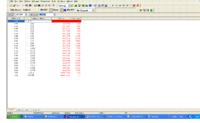
I got following result that i store in array.(See image)

Difference between two period is 198.
My internal frequency is 16MHZ and enable the PLL i.e 64MHZ

Please tell me how to calculate the capture period to frequency.


Code:
/*PWM used to generate 60kHz successfully working
Capture also working but not checked correctly*/


#include<p18f87k22.h>
#include<capture.h>

void T1_ISR(void);
void CCP4_ISR(void);

unsigned int capture=0,Tmr1ifCnt=0;
unsigned int arr[20]={0};
unsigned char i=0,output=0;

#pragma interrupt chk_isr         // used for high priority interrupt only.

void chk_isr(void)
{
    if(PIR1bits.TMR1IF==1)        // Timer0 causes interrupt.....?
        T1_ISR();
        
    if(PIR1bits.TMR2IF==1)
     PIR1bits.TMR2IF=0;
        
     if(PIR4bits.CCP4IF==1)        // Timer0 causes interrupt.....?
        CCP4_ISR();
        
     
}

#pragma code HI_PRIO_INT=0x0008      // high priority interrupt location.

void HI_PRIO_INT(void)
{
  _asm
  goto chk_isr
 _endasm
} 
#pragma code

void T1_ISR(void)
{
//	capture = ReadCapture4();
	Tmr1ifCnt++;
	PIR1bits.TMR1IF=0;
}	

void CCP4_ISR(void)
{
	capture = ReadCapture4();
	PIR4bits.CCP4IF=0;
	arr[i] = capture;
	if(output==1)
	{
		output=0;
	}	
	else
	{
		output=1;
	}	
	LATJbits.LATJ5=output;
	if(i<20)	
	i++;
	else
	i=0;
}	

void main(void)
{
	OSCTUNE = 0X80;			// for internal osc with pll enable 0xC0;			
    OSCCON = 0X74; 			// for internal osc with pll enable 0x74;					             //16MHz
    OSCCON2= 0X00;
	INTCON = 0xC0;			//Enable GIE/PEIE = 1
	ANCON0=0x00;                   // make all analog channel as digital I/O.
    ANCON1=0x00;                   // make all analog channel as digital I/O.
    ANCON2=0x00;

    ODCON1=0x00;
    ODCON2=0x00;
    PADCFG1=0x20; 

    CM1CON=0x00;                    // comparator1 OFF.
    CM2CON=0x00;                    // comparator2 OFF.
    CM3CON=0x00;                    // comparator3 OFF.    
    MEMCONbits.EBDIS=1;
	
	IPR1=0x01;
	IPR2=0x00;
	IPR3=0x00;
	IPR4=0x02;
	
	TRISGbits.TRISG3 = 1;//ccp
	TRISGbits.TRISG4 = 0;//pwm
	TRISAbits.TRISA5 = 1;//ccp
	TRISJbits.TRISJ5 = 0;//ccp
	
	CCP5CON = 0x00;
	CCP5CON = 0x0F;
	
	
	//PWM FOR 60kHz //60606.06Hz
	PR2 = 0b01000001 ;
	T2CON = 0b00000100 ;
	CCPR5L = 0b00100000 ;
	CCP5CON = 0b00111100 ;
	
	/*
	PR2 = 0b01011000 ;
T2CON = 0b00000100 ;
CCPR5L = 0b00101100 ;
CCP5CON = 0b00011100 ;
*/
	
//	PIE4bits.CCP4IE = 1;  //ccp
	//OpenCapture4(CAPTURE_INT_ON | CAP_EVERY_RISE_EDGE); //useless

	CCP4CON=0x04;//ccp
	PIE4bits.CCP4IE=1;//ccp
	T1CON = 0x02;//ccp			//Timer1 clock source from T1cki, prescaler 1:1, SOSC is disable, T1sync=0,RD16=1,Enable timer1.
	TMR1H=0x00;//ccp
	TMR1L=0x00;//ccp
	
	T1CONbits.TMR1ON=0;
	
	Tmr1ifCnt=0;
	i=0;
//	while(PORTAbits.T1CKI==0);
	T1CONbits.TMR1ON=1;
		
	scan:
	
	if(PIR1bits.TMR1IF==1)        // Timer1 causes interrupt.....?
        T1_ISR();
    
   	goto scan;
	
}        

/*
void filter_logic()
{
   unsigned char i,j;
   if(num_sample<3)
     {
      num_sample=3;
//      write_intval_eeprom(4,num_sample_addr,num_sample);
     }
   if(num_sample>40)
   {
    num_sample=40;
//    write_intval_eeprom(4,num_sample_addr,num_sample);
   } 
    min=arr1[1];
     max=0;
     max_location=0;  
     min_location=0;
   for(i=1;i<=(num_sample-1);i++)
     arr1[num_sample-i+1]=arr1[num_sample-i];
    arr1[1]=final_adc_result;
  
  for(i=1;i<=num_sample;i++)
  {
   if(arr1[i] > max)
   {
     max=arr1[i];
     max_location=i;
   }
  }
  for(i=1;i<=num_sample;i++)
  {
   if(arr1[i] < min)
   {
     min=arr1[i];
     min_location=i;
   }
  }
 j=1;
 for(i=1;i<=num_sample;i++)
 {
   if((i != min_location)&&(i != max_location))
   {
      arr2[j]=arr1[i];
      j++;
   }
 }
total=0;
for(i=1;i<=(num_sample-2);i++)
    total=total+arr2[i];
   avg_reading=(total/(num_sample-2));
  

}

*/
 

Can you please tell me what is the maximum input frequency to the T1CKI pin?

I used timer 1 as a free running timer to capture input frequency.
When i give 1MHz input to this pin my input freq which is 1K is calculate in time period of 1000 / 1001, there is +-1 hz error that i don't want.
I required 0.1 Hz accuracy for that i am giving 10Mhz input to the T1cki pin, but the count suffers.

Can u suggest another way?
 

Status
Not open for further replies.

Part and Inventory Search

Welcome to EDABoard.com

Sponsor

Back
Top