Continue to Site

Welcome to EDAboard.com

Welcome to our site! EDAboard.com is an international Electronics Discussion Forum focused on EDA software, circuits, schematics, books, theory, papers, asic, pld, 8051, DSP, Network, RF, Analog Design, PCB, Service Manuals... and a whole lot more! To participate you need to register. Registration is free. Click here to register now.

How to use a Hex Inverter (74LS04)

Status
Not open for further replies.

amirox

Newbie level 3
Joined
Jan 15, 2012
Messages
4
Helped
0
Reputation
0
Reaction score
0
Trophy points
1,281
Activity points
1,328
I want to invert a single coming from each pin of my arduino board. The goal is to keep motor Q2 running until a signal from PIN 1 is pulled up. In that case Motor Q2 must turn off and Motor Q2 turn on.

Here is my schematic made by a friend:
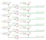
Fan Schematic.png

I am using SN74LS04 (Hex Inverter) that gives me 6 pairs of input output pins:
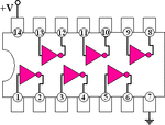
58_1307327849.gif

For some reason I can not get it to work. Instead of the motors and transistors I am using LED lights for testing. Vcc and Ground pins of the Inverter is connected to 5v pin and GND pin of arduino. Before going further, I read 1.2v on all input pins of the inverter (ie pin 1), and 0.15v on outputs (ie pin2).

Connecting 5v to the inputs does not make any difference in the output!!! I am confused. I was PIN2 (output) to be high unless I pull up PIN1 (input).

Any idea?
Thx for reading.
 

Try shorting the input to ground (or use a resistor if you're faint-hearted). Force the input voltage to be zero. See if the output goes high, which it should.

---------- Post added at 14:34 ---------- Previous post was at 14:03 ----------

If you have LEDs connected to the outputs, disconnect them and measure voltages. The 74LS04 is a low-power, and thus low-current device.
 

    V

    Points: 2
    Helpful Answer Positive Rating
Are you using current limiting resistors for the LED's on the output lines? The output voltage could be loaded down because to much current is trying to flow. Put a 1K resistor in series with the LED to limit the amount of current flow through the LED.
 

Valid points mentioned above.

Your schematic shows no resistor at the base of the transistors. Usually a resistor is needed to limit bias current.

You report 1.2 V on those wires. If there were no resistors you ordinarily should read 0.6 V. So perhaps your schematic is a simplified schematic?

In any case you must install components to make sure the signal swings up and down by a few volts. The 7404 inputs need to have the signal go above and below certain volt levels, in order for it to decide whether the incoming signal is hi or low.

Okey, everything works now.

I put a 1k resistor to ground at each input pin of the Inverter. It is working find now (not sure if 1k is correct though). There are no LEDs. As per schematic in the first post, I am using TIP120 transistors to run 12v. 0.4 ma motors.

Currently there is no resistor between TIP120 and the signal I am sending from Arduino output pin. Why would I need one there?
 

The base of the transistor will be clipped by the base-emitter junction of the transistor so the input of the inverter will NEVER go high. It will be limitted to around 0.8V ( depending slightly on the current).
You need a resistor so that the base of the transistor can be at 0.7V while the inverter input is at logic high.
 
Last edited:

I agree with DartPlayer170.

Another reason for putting a resistor at the transistor bases:

Going by the schematic, your arduino outputs send current to the transistor bases, which then goes out the emitter leg, directly to ground. That means a single diode junction lies between the arduino and ground. I would imagine it draws overmuch current from all your arduino output pins.

This is why it's a good idea to insert resistors at all the transistor bases, even though you say the setup works at present.
 

'
Currently there is no resistor between TIP120 and the signal I am sending from Arduino output pin. Why would I need one there?

One reason would be keeping the Arduino's IO port maximum ratings and prevent damage of the processor. Your circuit is only working at all (with good weather and tail wind or so), because you have TIP120 darlington transistors, that allow a port high voltage at least between specified low and high logic levels.
 

Status
Not open for further replies.

Part and Inventory Search

Welcome to EDABoard.com

Sponsor

Back
Top