Continue to Site
Follow along with the video below to see how to install our site as a web app on your home screen.
Note: This feature may not be available in some browsers.
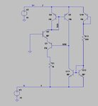
Hi, you can start by calculating the current through R13.
Yes, it is easy to calculate the current through R13.
But how to calculate the voltage of AAA and current through the Q4 Q2 Q1 ?
How about R1 affect the bias voltage and current??
No. All transistors are carrying the same current (ignoring small differences caused by finite B). It's about 0.73 mA - and set by R13.The collector voltage of Q1 = -Vbe(Q2) - Vcesat(Q1) ≈ -0.7V - 0.3V = -1V
Hence the current through Q4 Q2 Q1 & R1 is 14mA .
No. All transistors are carrying the same current (ignoring small differences caused by finite B). It's about 0.73 mA - and set by R13.
It isn't. Instead the current of Q4 is controlled by Q1. It's not a simple current mirror, it's a kind of Wilson current mirror (with additional cascode). Review your text books for it.What confused me is that why the current of Q4 is determined by Q9?
It isn't. Instead the current of Q4 is controlled by Q1. It's not a simple current mirror, it's a kind of Wilson current mirror (with additional cascode). Review your text books for it.
Wilson current mirror - Wikipedia, the free encyclopedia
Yes, I mentioned it has an additional cascode. If you understand the Wilson circuit, you'll see, that the control method of your circuit is basically the same.but my circuit is not same with the Wilson current mirror
Yes, I mentioned it has an additional cascode. If you understand the Wilson circuit, you'll see, that the control method of your circuit is basically the same.
I don't feel a need to argue how much different the circuit is from a Wilson current source. Obviously a Wilson current mirror doesn't need a cascode. My point was, that the current control mechanism is similar to a Wilson current source, it's not changed by an additional cascode transistor. Did you understand this point?I don't think it's the same.
The Wilson don't need any cascode because there MUST be all Vbe drop. A cascode here only shows a drop of Vce, it's doesn't make sense.