long88
Member level 3
Hi All,
I am very new about the opto triac driver circuit. My intention is to use a microcontroller I/O to switch the 240VAC signal to control a solenoid coil . The solenoid coil require a input of 240VAC, 50 - 60Hz and 80ma. After I done my research, I find that opto-triac and mechanical relay are very common to use in this kind of application. As I compare this two methods, I think that the opto triac methods is more suitable if compare to mechanical relayfor long term purpose.
Thus, i have brought a few pieces of K3012p opto triac (**broken link removed**). I manage to turn on the opto triac and output 240Vac signal to power up the solenoid coil . However, I fail to switch off 240Vac although I did set my control signal to low.
I read from some documents, it mention that the triac can turn off only if the current flow through triac is smaller than the holding current plus a low signal input to Vgate or a zero voltage across triac plus low signal input to Vgate. Please advice me whether my concept is correct.
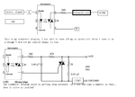
I attached my schematic(fail to turn off AC output) and a schematic (from internet). Please advice me whether the schematic (from internet ) able to solve the switching off issue.
Question to schmetic (from internet):
1. How this circuit able to turn off the Triac?
2. I read few data sheet regard the specification of triac. The Vgate signal is always a DC signal. From the schematic (from internet), it use the opto-triac ouput a signal (Is this a AC signal?) to feed in to the gate control of a triac.
3. Can I use 240VAC signal to feed into to the gate as a control signal to drive a triac?
Sorry, I am really not very familiar with the opto-triac. I really appreciate if you guys lecture me on this part.
Thank you very much
I am very new about the opto triac driver circuit. My intention is to use a microcontroller I/O to switch the 240VAC signal to control a solenoid coil . The solenoid coil require a input of 240VAC, 50 - 60Hz and 80ma. After I done my research, I find that opto-triac and mechanical relay are very common to use in this kind of application. As I compare this two methods, I think that the opto triac methods is more suitable if compare to mechanical relayfor long term purpose.
Thus, i have brought a few pieces of K3012p opto triac (**broken link removed**). I manage to turn on the opto triac and output 240Vac signal to power up the solenoid coil . However, I fail to switch off 240Vac although I did set my control signal to low.
I read from some documents, it mention that the triac can turn off only if the current flow through triac is smaller than the holding current plus a low signal input to Vgate or a zero voltage across triac plus low signal input to Vgate. Please advice me whether my concept is correct.
I attached my schematic(fail to turn off AC output) and a schematic (from internet). Please advice me whether the schematic (from internet ) able to solve the switching off issue.
Question to schmetic (from internet):
1. How this circuit able to turn off the Triac?
2. I read few data sheet regard the specification of triac. The Vgate signal is always a DC signal. From the schematic (from internet), it use the opto-triac ouput a signal (Is this a AC signal?) to feed in to the gate control of a triac.
3. Can I use 240VAC signal to feed into to the gate as a control signal to drive a triac?
Sorry, I am really not very familiar with the opto-triac. I really appreciate if you guys lecture me on this part.
Thank you very much