Continue to Site

Welcome to EDAboard.com

Welcome to our site! EDAboard.com is an international Electronics Discussion Forum focused on EDA software, circuits, schematics, books, theory, papers, asic, pld, 8051, DSP, Network, RF, Analog Design, PCB, Service Manuals... and a whole lot more! To participate you need to register. Registration is free. Click here to register now.

how to the termination and excitation of wire antenna

Status
Not open for further replies.

h_cet

Member level 4
Joined
Jan 25, 2006
Messages
69
Helped
0
Reputation
0
Reaction score
0
Trophy points
1,286
Activity points
1,771
hi,

I need to know how to do the termination and excitation of wire antenna. According to hfss tutorial, I know that if we want that microstrip antenna is terminated by 50 ohm, we have to draw a rectanguler which is defined RLC port or to be defined a wawe port and integration line is drawn from line to ground.

But wire antenna doesnt have a ground. So, I am not able to define its 50 ohm terminator load and excitation.

please can you tell how ı should define its 50 ohm terminator load and excitation in wire antenna?

thanks for your helps......


heeey

doesnt anybody know how to define the terminator load and excitation for wire antenna?


please heeellp meeee
 

Dear h_cet,

For your situation, maybe what you can try is:

At the input end to your wire antenna, draw a coax and assign it as a waveport that you seem to know of.

At the termination end of your wire antenna, do a small break just before reaching the end of the wire. Then at the break, assign a lumpedRLC 50 ohm boundary.

I really don't know whether this will work, because the fact that you don't even have a finite sized ground plane still puzzles me.

Hope this helps,
Dave
 

hi heedavid,

first of all thank you very much for your helps...

I am not able to understand one of your important explanations. you said that "you did a small break just before reaching the end of the wire." can you tell me it in a picture?

really I need it....

I will try them....

again thanks....
 

Dear h_cet,

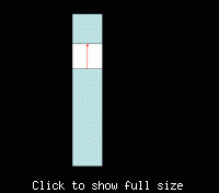
Sorry for the delay. This is what I meant:

60_1187317882_thumb.gif


https://obrazki.elektroda.pl/60_1187317882.gif

I still couldn't get over the part of your design not having a ground-plane. I don't know if this will work when you don't have a ground for your LumpedRLC 50 ohm boundary's other end. Do elaborate more the next time if you got the chance, as to why you don't need a ground-plane in your design.

Hope this helps,
Dave

P.S.: BTW, the whole simulation structure I've drawn out should be in 2D. 3D is also do-able.
 

hi heedavid,

thankks for your helps ,,
Iwill try it immediately

thanks
 

Hi mr Heedavid,
I ve sent you a pm, plz check your box, thanks very much !!
 

Status
Not open for further replies.

Part and Inventory Search

Welcome to EDABoard.com

Sponsor

Back
Top