Continue to Site

Welcome to EDAboard.com

Welcome to our site! EDAboard.com is an international Electronics Discussion Forum focused on EDA software, circuits, schematics, books, theory, papers, asic, pld, 8051, DSP, Network, RF, Analog Design, PCB, Service Manuals... and a whole lot more! To participate you need to register. Registration is free. Click here to register now.

How to solve Transformer 0-22V ac Flat top in the Sinewave - Reg

Status
Not open for further replies.

prakashvenugopal

Advanced Member level 1
Joined
Jun 1, 2011
Messages
473
Helped
15
Reputation
30
Reaction score
15
Trophy points
1,298
Activity points
4,973
Hi all,

Transformer Details:

Primary : 0-200-220-240V / 2A

Secondary1 : 24-22-20-0-20-22-24V / 72VA

Secondary2: 0-16.5 / 16.5VA


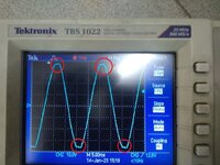
I had Found Primary Waveform 0-220v ac is Pure sine-wave and Found Flat Topping in the Sine-wave of 0-22Vac Secondary Tx as we attached in the image.

I had measured the current Waveform also and it is attached in the Video for your reference.

Kindly let us know how to avoid this Flat topping in the Transformer Secondary Waveform.

Regards,
V. Prakash
 

Attachments

  • Flat Top in 0 - 22 V ac.jpg
    Flat Top in 0 - 22 V ac.jpg
    174.2 KB · Views: 158
  • Current Vs Secondary Voltage 0 - 22V.mp4
    4 MB

Distorted input current and flattened output voltage are both caused by rectifier filter capacitor and are unevitable with this power supply circuit topology.

There is a dependence on transformer series impedance X% and R%. The higher the impedance the stronger output voltage flattening but the lower current THD.

Since power quality regulations are constraining current THD, simple single phase rectifier circuits above a certain power level became problematic. These days, most EMC aware single phase AC/DC are using active PFC, some older devices are scarcely complying standards with a series choke.
Hi,

Thanks for the reply.

Is there any Single Phase AC/DC using Active PFC to test? Kindly share.

Regards,
V. Prakash
--- Updated ---

Those harmonics have nothing to do with the quality of the DC out of the regulator.

How is it making you system malfunction?
What does the DC signal look like from the regulator?
Hi,

I am measuring the THD in the Transformer Secondary using the THD Meter which is showing high when compared to the Transformer Primary and also the Amplifier output Signal is giving noise signal instead of stable signal. DC signal is stable with the +18V DC with 150mV ac ripple and -18V DC with +150mV ac ripple

Regards,
V. Prakash
 
Last edited:

I am measuring the THD in the Transformer Secondary using the THD Meter which is showing high when compared to the Transformer Primary
Implausible, most likely a wrong measurement. Primary and secondary transformer currents are closely linked.

Seeing 50 Hz and its harmonics in amplifier output is a matter of unsuitable ground layout or possibly unsufficient filtering of preamplifier supply. I presume that 150 mV supply ripple is within your specs. If not clarify with a circuit schematic.
--- Updated ---

If your rectifier circuit involves a transformer center tap, secondary THD will be higher by design.
Hi,

150mV ripple is within the specification only.
I had attached the Powersupply Section circuit for your reference.

Regards,
V. Prakash
 

Attachments

  • PowerSupply Section Circuit.jpg
    PowerSupply Section Circuit.jpg
    109.4 KB · Views: 71

150 mV ripple after linear regulator is not good. Sure the unregulated DC provides sufficient voltage margin for the regulator? Did you watch it on oscilloscope?

What's the purpose of extra series diodes?
 

150 mV ripple after linear regulator is not good. Sure the unregulated DC provides sufficient voltage margin for the regulator? Did you watch it on oscilloscope?

What's the purpose of extra series diodes?
Hi,

I am testing in the Oscilloscope. I have not used the Extra Series diode in the PCB. It is shorted with Jumper.

Regards,
V. Prakash
 

Status
Not open for further replies.

Similar threads

Part and Inventory Search

Welcome to EDABoard.com

Sponsor

Back
Top