Continue to Site

Welcome to EDAboard.com

Welcome to our site! EDAboard.com is an international Electronics Discussion Forum focused on EDA software, circuits, schematics, books, theory, papers, asic, pld, 8051, DSP, Network, RF, Analog Design, PCB, Service Manuals... and a whole lot more! To participate you need to register. Registration is free. Click here to register now.

how to simulation differential filter by ads,plz help

Status
Not open for further replies.

luciforlove

Member level 1
Joined
Sep 12, 2012
Messages
41
Helped
3
Reputation
6
Reaction score
3
Trophy points
1,288
Activity points
1,535
recently i study differential filter,but i only simulate single-ended signal before.
could anyone give me some pdf to show how to simulate differential filter by ads,thanks in advance!
 

Hi,

I hope you know the process of converting single ended filter to differential filter. If not, then follow this document which will give you some idea on how to convert single ended filter to differential.

https://www.ti.com/lit/an/slwa053b/slwa053b.pdf

50 ohm filter.png

where L1 L2 L3 L4 L5 are inductors and C1 and C2 are capacitors.

The filter was designed for 50ohm impedance matching both for input port and output port.

After conversion to differential filter the result is this:

100ohm differential.png

So let us say in order to design 100 ohm differential filter you have to first synthesize 50 ohm single ended filter and then convert it to differential.

From simulation perspective, you have to remove ground pins from port termination and connect it to your circuit. Attached image.

Differential Filter.png

I hope this will help you to start your simulations in ADS.

Let me know if you need any more information.

Cheers,
Antonio.
 
Hi,

I hope you know the process of converting single ended filter to differential filter. If not, then follow this document which will give you some idea on how to convert single ended filter to differential.

https://www.ti.com/lit/an/slwa053b/slwa053b.pdf

View attachment 85328

where L1 L2 L3 L4 L5 are inductors and C1 and C2 are capacitors.

The filter was designed for 50ohm impedance matching both for input port and output port.

After conversion to differential filter the result is this:

View attachment 85329

So let us say in order to design 100 ohm differential filter you have to first synthesize 50 ohm single ended filter and then convert it to differential.

From simulation perspective, you have to remove ground pins from port termination and connect it to your circuit. Attached image.

View attachment 85327

I hope this will help you to start your simulations in ADS.

Let me know if you need any more information.

Cheers,
Antonio.

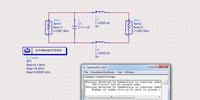
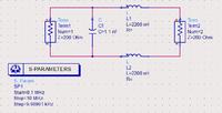
thank you ,your pdf really helps me a lot ,here is what i do,but i dont know if am i right
1255659100_1357538084_thumb.jpg

1632063600_1357538085.jpg

there is some warning,should i ingnore it?
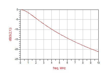
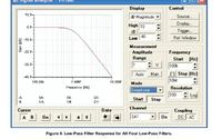
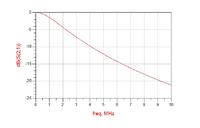
and my result is not the same as the pdf'image,on pfd'image s21 is -40dB on 10MHz,my result is -20dB on 10MHz,so i feel like i didnt do it the right way,please help me
1636119200_1357538478_thumb.jpg


- - - Updated - - -

 
Last edited:

Hi,

I am happy that pdf helped you in getting understanding about single ended to differential filter conversion. :)

First of all I am not able to view any of your uploaded images in large size. So it is very difficult for me to comment on what did you synthesized and what did you simulated in ADS.

1. Could you please update on filter specifications you are trying to meet and also upload images properly so that I can view them properly ?

2. What was your synthesis impedance ?

3. Yes, you can ignore the warning as it will look for ground node.

4. What tool are you using for synthesis ?

Please give some information as requested above so that I can help you better.

Cheers,
Antonio

i did it just as pdf told me.

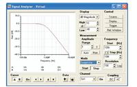
and the pdf'image shows there shoud be -40dm on the freq of 10MHZ as below:

but when i simulate it by ads as below:

https://obrazki.elektroda.pl/2698684200_1357723796.jpg
the result is different,only -20db at 10MHZ

PLEASE,HELP ME,thank you
 

Your ADS schematic has 2.2µH instead of 22µH.
 

Status
Not open for further replies.

Part and Inventory Search

Welcome to EDABoard.com

Sponsor

Back
Top