kudzus
Newbie level 2

Hello, Dear friends
I want to simulate the classical class-E power amplifier. I set the DC voltage Vdd=25 V, output power Po=6 W; the quality factor QL=7; and the operational frequency f=1MHz. The transistor is IRF510.
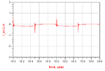
The parameters are calculated as: R= 60.0834; Lf=69.938u; Cf=453p; C=486pF(the transistor output capacitor is 250p); and the chock is 416u. I added all this elements into the ADS. However, only the switching voltage is correct. The maximum value of the output voltage is wrong. The waveform of the switching current is wrong.
How to correct the circuit to output the right switching voltage and current? (I thoght an input matching needed, But how to design the input matching network?
Another question is the QL is selected as 7. In real design, how to exactly control the quality factor?


 )
)
I want to simulate the classical class-E power amplifier. I set the DC voltage Vdd=25 V, output power Po=6 W; the quality factor QL=7; and the operational frequency f=1MHz. The transistor is IRF510.
The parameters are calculated as: R= 60.0834; Lf=69.938u; Cf=453p; C=486pF(the transistor output capacitor is 250p); and the chock is 416u. I added all this elements into the ADS. However, only the switching voltage is correct. The maximum value of the output voltage is wrong. The waveform of the switching current is wrong.
How to correct the circuit to output the right switching voltage and current? (I thoght an input matching needed, But how to design the input matching network?
Another question is the QL is selected as 7. In real design, how to exactly control the quality factor?


 )
)Attachments
Last edited:


