sirikphon
Newbie level 1
Hello,
I designed the 38 GHz dielectric resonator filter using CST microwave studio.
Now I have problem to set the boundary condition of dielectric resonator filter during simulation.
How to the set boundary condition? is it to set Et=0 or Open?
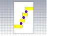
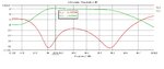
As attached is the designed of 38 GHz dielectric resonator filter and result with boundary condition set to Et=0.
upon fabrication of the design from CST, I measured them using Network Analyzer and the S-parameter results
is not the same with the S-parameter result from the CST. I meant the value such as S21 in CST= -1.63 dB but
in Network Analyzer is -20.215dB.
Thank you.::smile:
I designed the 38 GHz dielectric resonator filter using CST microwave studio.
Now I have problem to set the boundary condition of dielectric resonator filter during simulation.
How to the set boundary condition? is it to set Et=0 or Open?
As attached is the designed of 38 GHz dielectric resonator filter and result with boundary condition set to Et=0.
upon fabrication of the design from CST, I measured them using Network Analyzer and the S-parameter results
is not the same with the S-parameter result from the CST. I meant the value such as S21 in CST= -1.63 dB but
in Network Analyzer is -20.215dB.
Thank you.::smile: