Continue to Site

Welcome to EDAboard.com

Welcome to our site! EDAboard.com is an international Electronics Discussion Forum focused on EDA software, circuits, schematics, books, theory, papers, asic, pld, 8051, DSP, Network, RF, Analog Design, PCB, Service Manuals... and a whole lot more! To participate you need to register. Registration is free. Click here to register now.

[SOLVED] Shunt reactive loading of a series resonator

Status
Not open for further replies.

afz23

Full Member level 3
Joined
Nov 30, 2007
Messages
183
Helped
15
Reputation
30
Reaction score
14
Trophy points
1,298
Location
Bangalore
Activity points
2,758
Hi ,

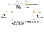
I was reading about a simple resonator design and found a relation of shunt reactance to set loaded Q of series
resonator in a 50 ohm system to a desired value.

I tried a few times,but some how I am not getting this 'Xshunt' relation,when I solve it on my own.

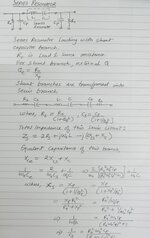
Same relation is mentioned in the reference book by Vendelin,but there also direct formula is given not the derivation.

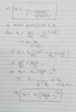
I need help to understand the procedure to get Xshunt formula as mentioned in the attached design here.

I hope this is well known to resonator designers,kindly throw some light on this formula.

thanks
 

Attachments

  • shunt loaded series resonator.pdf
    192.6 KB · Views: 57

Since source and load are both equal, half power or -6 dB in voltage at series resonance where X(f) for L is +ve= C which is -ve and cancel out to null.

This is the same model for ceramic and crystal resonators except they have fF in series called crystal lattice "motional capacitance". > 99% of the power only goes thru the series LC circuits and < 100 uW goes thru the shunt caps here at resonance while 5 Watts goes thru this lossless series LC with 5Vp sine. So the shunt caps have very tiny amounts of frequency shift compared to the series cap which does all the work which is ideally 0 ohms at resonance while shunt caps are much higher impedance.

1702179822561.png

In this simulation you can change any component value with the mouseover with wheel.

If you move the output to the center of series LC , observe the huge gain. This why they say to limit power in crystal to 100 uW or less, because it can generate many kV from Q= 10,000 inside the crystal lattice and arc and damage it due to internal series R without suitable series current limit. ( but you cannot see or feel it burn.) Here it is just a passive BPF (bandpass filter) at 5MHz with high Q.

I hope this is more intuitive, if so, send me coffee or single malt

In the days of slide rules I used this graph paper to intuitively look up ballpark impedance or R, L, C ,f values and estimate Q for series or parallel filters.
( and I still use it )
This one was for another filter.
Series Q uses R lower than LC impedance. Parallel high Q resonance, load R is always higher than reactance.
1702180424807.png

;)
--- Updated ---

I cannot vouch for this formula and suspect it is wrong.
1702183356879.png


Basically Cshunt is irrelevant except where Cseries is smaller in a limited range and shunt values are mismatched.
 
Last edited:

Thanks Tony for giving an insight on the resonator functioning and taking time to upload/share these interesting graphs which you use for estimating RLC parameters.
You mentioned that series RLC require much lower source and load impedance to preserve the Q ,whereas parallel RLC require much higher
load and source impedance for the same.

How do you calculate this load/source impedance required for a particular loaded Q value and transform it to a combination of 50ohm load/source and a reactance?
Do you use some formula or any table for this calculation?

thanks and regards
Q = fo / -3dB BW = Real/Reactive power for parallel and Reactive/ Real for series only at fo.

Impedance is also proportional to Power (P=I^2R) so Impedance ratios are the same on the RLCf chart as 1 decade separation for Impedance for Q=10, 2 decades for Q=100

in this case the normalized loss is -6 dB so -3dB BW is at -9 dB if Rs = Rload.
 
Last edited:

thanks Tony,

I would like to re-frame my question as per the attachment in my initial query.

If an inductor has Qu=120,

I wish to have overall Q of this series inductive circuit, i.e. QL=15 in a 50 ohm system.

Now one way to get the desired QL is by adding shunt capacitors on both the sides of this inductor.

finally the LC series should resonate at 1GHz with QL=15.

I need to find values of this shunt capacitors.
 

Attachments

  • reso23.png
    reso23.png
    15.3 KB · Views: 45

Same thing except comparing energy stored/lost so 1/2 LI^2 / DCR = Q(L)

For fo chosen derive loss resistance or look up DCR and add to total model.
Same for C, ESR.

Combine all series resistance to compute circuit Q by impedance ratios for series resonance, which is current loss. X{L, fo} / Req = Q = |X{C, fo}|

Get it?
 

thanks Tony,

I wish to have overall Q of this series inductive circuit, i.e. QL=15 in a 50 ohm system.

finally the LC series should resonate at 1GHz with QL=15.

I need to find values of this shunt capacitors.
To answer the question, 1 GHz center frequency results from Farad values 22 pF.

However the LC ratio makes a difference as to Q. This demo simulation shows various LC ratios and how they affect bandpass curve . Sine sweep in the vicinity of 1 GHz. 50 ohms series resistance.

This suggests a 10nH inductor would give you a gentle sloping rolloff curve (low Q) in a 50 ohm system.

LC bandpass 3 ratios 50 ohm series sweep 500M to 2000MHz.png


Click the link below to run the above in Falstad's animated interactive simulator:

1) Navigates to website Falstad.com/circuit
2) Loads my schematic into the program
3) Runs it on your computer

tinyurl.com/ytdo9tk5

Test any values you wish by right-clicking on component, select Edit.
Toggle full screen (under File menu).
Enlarge scope traces by dragging upward with mouse on border of scope area.
 

Hi Guys ,
Thanks for your response.
Finally I could derive expression for 'Xshunt' mentioned as Xp in the derivation. This I am posting for the benefit of our forum members.
Pl note that original query was to derive expression for shunt reactance to get desired loaded Q of series resonator circuit in a 50 ohm system, here Ro is 50 ohm.

regards
 

Attachments

  • IMG_20231214_163757.jpg
    IMG_20231214_163757.jpg
    3.6 MB · Views: 38
  • IMG_20231214_163513.jpg
    IMG_20231214_163513.jpg
    2.6 MB · Views: 47

Status
Not open for further replies.

Part and Inventory Search

Welcome to EDABoard.com

Sponsor

Back
Top