Continue to Site

Welcome to EDAboard.com

Welcome to our site! EDAboard.com is an international Electronics Discussion Forum focused on EDA software, circuits, schematics, books, theory, papers, asic, pld, 8051, DSP, Network, RF, Analog Design, PCB, Service Manuals... and a whole lot more! To participate you need to register. Registration is free. Click here to register now.

[SOLVED] How to remove DC offset from PWM signal ?

Status
Not open for further replies.

giovaniluigi

Member level 1
Member level 1
Joined
May 30, 2009
Messages
32
Helped
0
Reputation
0
Reaction score
0
Trophy points
1,286
Visit site
Activity points
1,626
I need to read a PWM pulse frequency from an industrial sensor with a MCU.
In order to isolate and protect the MCU port I've used an opto-coupler and to drive the LED from opto-coupler I've used a bipolar transistor.
The output from sensor then, enters into the base of transistor, which drives the opto-coupler LED, which drives the photo-transistor and finally reach to the MCU input port.

That would be the "sequence followed" by the signal:
[SENSOR] -> [BJT] -> [OPTO-COUPLER] -> [MCU]

The problem is that I have a DC offset coming from the sensor.
That small DC offset is about 1V, and it is enough to bias the BJT's base, thus the BJT is always conducting.
The signal from sensor is weak and can't drive directly the LED from opto-coupler, that is why I'm using the BJT.

I thought in using zenner diodes to solve this, but once the sensor can't provide too much current, I think that this diode may cause some problems.
I just want to recreate a simple hysteresis from a logical port.
How can I remove that offset or introduce some hysteresis in input stage of my circuit ?
 

I suggest just getting the signal to a level the MCU will tolerate and with optoisolation if you need it. Then, use the edge-triggered CCP module with a timer (e.g., TMR1) to "read" the pwm. If you are doing it in MPASM, I can share some code with you that is for a 12F683, but can be easily adapted to any 12F or 16F device.

John

Well, actually I'm using a timer to measure the pulse. That is not the issue.
The question is about the HW part.

How can I deal with the input signal of 0 / 10V to translate to logic values and also allow some margin/tolerance for logic OFF.

Thanks
 

  • Like
Reactions: FvM

    FvM

    Points: 2
    Helpful Answer Positive Rating
Depending on the voltage available, you can put 1 or 2 diodes in the emitter to ground connection. This will raise the floor for the Vbe_sat. You could also add a pulldown resistor to the base of the transistor, making a divider. This depends on the avialable voltage output Level. I suppose you are driving the LED in the optocoupler in series with a current limiting resistor, between Vcc and collector, and use a NPN transistor.
 

Depending on the voltage available, you can put 1 or 2 diodes in the emitter to ground connection. This will raise the floor for the Vbe_sat. You could also add a pulldown resistor to the base of the transistor, making a divider. This depends on the avialable voltage output Level. I suppose you are driving the LED in the optocoupler in series with a current limiting resistor, between Vcc and collector, and use a NPN transistor.

Thanks for your idea.

I'm using a npn BJT with the limiting resistor on LED as you described.

Actually raising the floor of Vbe_sat could work well, but sounds like a kludge.
BTW, I could achieve the same solution by connecting the diode in series with the sensor.

I found something interesting.
I can't use a common IC schmitt trigger because of voltage levels...
However, I could try to implement a schmitt trigger with a single op-amp.

Like this:
theschmitttrigger_1261499638.png

What do you think guys ?
 

First of all, you need to use a comparator, not opamp for this. Then the trigger level needs to be defined, since you say the idle Level is around 1V you need at least to set the trigger Level above that. Last and not least is the power supply requirement for the comparator IC. Comparators are normally open collector and this should work together with the optocoupler LED, but to use this you need to make the Schmitt trigger inverting.
 
Most essential informations haven't yet been revealed, like
- guaranteed logic low and high levels of the "sensor" output
- available supply voltage for the level converter/LED driver
- is there any substantial reason to use a schmitt trigger besides your problems to figure out a simple level converter circuit

ok,

1.
Well, this sensor has not very well defined levels.
The output of SENSOR, consists in a LM258 with a limiting resistor in series of 250ohm
([SENSING ELEMENT] -> [LM258] -> [RES. 250ohm] -> OUTPUT)
Sensor was not made by me. Thus I can't change it
For 12V supply the levels are 10V = HIGH (0~1V) = LOW

2.
Level converter/LED driver has up to 12V available on my circuit.

3.
I need an hysteresis into that input circuitry.
I need to ignore any level up to 1V.
Right now the input is going directly to the base of BJT.

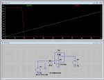
I did one simulation here:
op-amp schmitt trigger.JPG
In this example the tolerance is set to 2V.
Green LINE = input (from sensor)
Red LINE = output to LED driver

- - - Updated - - -

First of all, you need to use a comparator, not opamp for this. Then the trigger level needs to be defined, since you say the idle Level is around 1V you need at least to set the trigger Level above that. Last and not least is the power supply requirement for the comparator IC. Comparators are normally open collector and this should work together with the optocoupler LED, but to use this you need to make the Schmitt trigger inverting.

I was going to use a comparator, but then I found on internet some schematics referring to op-amp as a basis for the schmitt trigger. I've simulated on LTSPICE and seems to work.

What comparator IC would you suggest to drive the LED from opto-coupler directly (if possible) ?
It would need to supply at least 10mA for that LED requirement.

Thanks.
 
Last edited:

According to your specification, any threshold between e.g. 3 and 7 volts should work. So a CD4000 series schmitt trigger (CD4093) would work. Also any ST circuit built from two transistors and a few resistors around it.
 
According to your specification, any threshold between e.g. 3 and 7 volts should work. So a CD4000 series schmitt trigger (CD4093) would work. Also any ST circuit built from two transistors and a few resistors around it.

Yeah I agree with you completly.
Actually I thought on that IC family before, but I never worked with them that I even remembered the name.
(I'm a software guy)
I was looking for an alternative to the IC, but after some research seems that I would need to use an IC anyway.
The alternative is the 2 transistor configuration, but perhaps the single IC is better.
Is there any modern IC with smaller footprint than those "old" CD4000 ? May be with a single comparator...
Thanks for the tip.
 

High voltage CMOS logic isn't available as small "single-gate" device. When small size is an objective, you'll end up with analog comparators or discrete transistor circuits. You can roughly achieve similar size with both solutions, I think. E.g. one sot23-6 package and a few resistors.
 

Status
Not open for further replies.

Similar threads

Part and Inventory Search

Welcome to EDABoard.com

Sponsor

Back
Top