Pratik_S
Newbie level 3
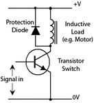
I have implemented the circuit attached along on a breadboard. i have used BC547 npn transistor and 4007 diode a 12V battery (power supply) and a 12V , 60 RPM , DC motor as an inductive load. My main aim is to calculate the back emf that the motor generates and after that i want to verify if it is being reduced or eliminated by adding a freewheeling diode in the circuit as shown. If any one out here could explain me in simple terms would be of great help. Thanks in advance!
Experiments that i have tried are:-
1. I removed the freewheeling diode and checked the voltage across the motor on the DMM by turning it ON and OFF expecting that while disconnecting the battery terminals i would get a negative voltage value for few seconds till the motor stops rotating. But i didn't see such a response. Is this the right method?
2. Then i tried the other method :-
As soon as the coil in the motor starts rotating , a back emf will be induced in it due to the flux that it cuts , and this will tend to reduce the current through it,
let the supply emf be 'E'
the bck emf be 'e'
Resistance of the coil be 'R' and
the current be 'I'
then, I=[E-e]/R ...(i)
since e is directly proportional to angular speed 'w'
as there is increase in angular speed the current will decrease
SO i measured the resistance of the motor by putting an ammeter and a voltmeter as shown in the second attachment.
After the results seen on the ammeter i calculated the Resistance , by V=IR ;
and then substituted these values of I,R and E in the formula (i) still the result i got was e=0 with the freewheeling diode and without the freewheeling diode in the circuit.

