Continue to Site

Welcome to EDAboard.com

Welcome to our site! EDAboard.com is an international Electronics Discussion Forum focused on EDA software, circuits, schematics, books, theory, papers, asic, pld, 8051, DSP, Network, RF, Analog Design, PCB, Service Manuals... and a whole lot more! To participate you need to register. Registration is free. Click here to register now.

How to measure the back emf of a dc motor and how to eliminate it?

Status
Not open for further replies.

Pratik_S

Newbie level 3
Joined
Apr 14, 2015
Messages
3
Helped
0
Reputation
0
Reaction score
0
Trophy points
1
Activity points
31
I have implemented the circuit attached along on a breadboard. i have used BC547 npn transistor and 4007 diode a 12V battery (power supply) and a 12V , 60 RPM , DC motor as an inductive load. My main aim is to calculate the back emf that the motor generates and after that i want to verify if it is being reduced or eliminated by adding a freewheeling diode in the circuit as shown. If any one out here could explain me in simple terms would be of great help. Thanks in advance!

Experiments that i have tried are:-
1. I removed the freewheeling diode and checked the voltage across the motor on the DMM by turning it ON and OFF expecting that while disconnecting the battery terminals i would get a negative voltage value for few seconds till the motor stops rotating. But i didn't see such a response. Is this the right method?

2. Then i tried the other method :-
As soon as the coil in the motor starts rotating , a back emf will be induced in it due to the flux that it cuts , and this will tend to reduce the current through it,
let the supply emf be 'E'
the bck emf be 'e'
Resistance of the coil be 'R' and
the current be 'I'
then, I=[E-e]/R ...(i)
since e is directly proportional to angular speed 'w'
as there is increase in angular speed the current will decrease
SO i measured the resistance of the motor by putting an ammeter and a voltmeter as shown in the second attachment.
After the results seen on the ammeter i calculated the Resistance , by V=IR ;
and then substituted these values of I,R and E in the formula (i) still the result i got was e=0 with the freewheeling diode and without the freewheeling diode in the circuit.
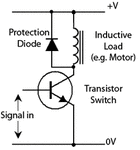
Protection-Diode.gifWIN_20150414_112955 (2).JPG
 

Hi,

to measure back emf you should temporary switch off the motor and then measure the voltage across the motor.
It usually is proportional to the speed of the motor. With a DVM it is almost impossible to measure, because the motor slows down before you have a meaningfull display value.

Do the measurement with a scope.
Usually you will see a short pulse to the opposite dirction caused by the inner inductivity. But this should be over within some tens of microseconds.
Don´t disconnect the protection diode, because this short pulse may kill your transistor.

***
another method to measure back emf is:
Measure (with low voltage) the inner DC_resistance of the motor when stalled. Use Ohm´s law.

then connect the motor and let it run.
now measure the current:

back_emf = applied_voltage - (current x DC_resistance)

I hope this is true .. it´s some ten years ago ... please try to find documentation on that.


Klaus

@klaus i will surely try this .. i hope it helps.. Thanks mate..
 

I suspect a confusion of terms. Back emf usually refers to the voltage generated by an inductive load that tries to maintain it's current when switched-off. Although a DC motor involves a certain amount of armature inductance that generates back-emf, at running motor will primarly generate a "forward" emf representing generatoric operation.

The freewheeling diode in the post #1 schematic will absorb back emf voltage spikes during switch-off. The emf of the rotating motor won't cause a diode current because it has opposite polarity.
 

Hi,

before my post i confirmed the phrase of "back emf on DC motors"
this is what en.wikipedia.org says (within the article "Counter-electromotive force")
The term back electromotive force, or just back-EMF, is most commonly used to refer to the voltage that occurs in electric motors where there is relative motion between the armature of the motor and the magnetic field from the motor's field magnets, or windings. From Faraday's law, the voltage is proportional to the magnetic field, length of wire in the armature, and the speed of the motor. This effect is not due to the motor's inductance and is a completely separate effect.

But i agree with FvM that with valves, relays and solenoids this is different.

The series inductance (both motors and solenoids) generates a negative voltage in relation to the activating voltage. Then the external diode will keep this voltage low.
the generated back_emf voltage of a DC motor is - as FvM said - in the same direction like the activating voltage.

Klaus
 

@klaus i will surely try this .. i hope it helps.. Thanks mate..

Thanks a ton Klauss it really helped me a lot.. Now that this is done i am trying it with a scope. Lets see how it works. haha..
 

If you disconnect the cathode of the protection diode and connect it to a capacitor which has its other side earthed, then as the motor commutates, this back emf will got through the diode and charge the capacitor. The DC can be measured across this cap with your DVM. So now starting off at say 1NF and increasing the caps value, the DC voltage can be plotted and hence a value determined for when the value of the cap = 0.
Frank
 

Status
Not open for further replies.

Part and Inventory Search

Welcome to EDABoard.com

Sponsor

Back
Top