Continue to Site

Welcome to EDAboard.com

Welcome to our site! EDAboard.com is an international Electronics Discussion Forum focused on EDA software, circuits, schematics, books, theory, papers, asic, pld, 8051, DSP, Network, RF, Analog Design, PCB, Service Manuals... and a whole lot more! To participate you need to register. Registration is free. Click here to register now.

how to light series of LEDs as a big 7 Segment Display using MC74HC595 and ULN2003

Status
Not open for further replies.

barbaro

Member level 3
Joined
Jun 20, 2011
Messages
57
Helped
0
Reputation
0
Reaction score
0
Trophy points
1,286
Activity points
1,734
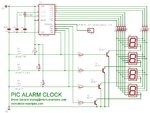
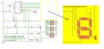
Hi I'm new to electronics and have never done any project. I'm just wondering if anyone can HELP on how to start/begin using MC74HC595 and ULN2003. I tried following the schem diagram for SPI Inetrface BIG 7 Seg LED by Wichit Siri but can't seem to have it working. Maybe I need to understand it further. What is "uC I/O" ? Any asistance will be appreciated.
 

The circuit uses a serial-in-parallel out shift register, 74HC595 for receiving serial data from uController board. See example of U5 in the schematic, SER is for data input, SRCLK is shift clock and RCLK is Latch clock. Each data bit is shifted into the register on rising edge of the shift clock. When all data bits are shifted into the 8-bit register, the rising edge of RCLK will clock the data to be latched at each output bit

**broken link removed**

So, in order to obtain some results, you need to have also a uController board.
 

**broken link removed**

So, in order to obtain some results, you need to have also a uController board.

Thanks... is there any specific code to use as uController board so I can buy.
 

Well, this part with the uController it’s tricky, not so complicated but also not so easy for a beginner. There are many clock-circuit projects requiring 7-segment display and keypad interfacing, and you need to choose one from the internet, to get the idea how to build a simple project, and maybe later to add some big displays.
 
To give you an idea about the required changes, let’s choose a normal clock, and to consider the modifications needed to add a large LEDs display.
Project here:
A PIC16F84A Alarm Clock

For the moment I have made only modifications for one digit, a complete diagram keep the transistors, adding more resistors and LEDs only. This is just a demo, in practice maybe we need to combine some LEDs in series…
 

Attachments

  • 084-ALARM-CLOCK-schematic.jpg
    084-ALARM-CLOCK-schematic.jpg
    125.4 KB · Views: 227
  • modified ALARM-CLOCK-schematic.JPG
    modified ALARM-CLOCK-schematic.JPG
    181.7 KB · Views: 213

To give you an idea about the required changes, let’s choose a normal clock, and to consider the modifications needed to add a large LEDs display.
Project here:
A PIC16F84A Alarm Clock

For the moment I have made only modifications for one digit, a complete diagram keep the transistors, adding more resistors and LEDs only. This is just a demo, in practice maybe we need to combine some LEDs in series…

Hi, Thanks again.

How about using 74LS47 and a UP/DOWN Resettable Counter...do you have any sample of schematic diagram that I can use?
 

Yes, it’s simple to do, need to choose a resettable counter.
See for example a circuit using CD4510 = BCD up/down counter.
**broken link removed**
 

Attachments

  • BCD counter.GIF
    BCD counter.GIF
    13.5 KB · Views: 177
Last edited:

Status
Not open for further replies.

Part and Inventory Search

Welcome to EDABoard.com

Sponsor

Back
Top