VINAY_RAO
Junior Member level 2
Hello all,
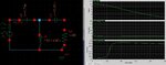
I have designed the T-match network to get resultant impedance of 2 Ohm out of 50 ohm load. I have plotted S11 & ZM (both mag & phase) and getting exact results (I have attached both circuits and simulated results). But one question is popping up in my mind about its behavior.
I take this circuit as some black box and connect the port to measure ZM. In the result, it can be observable that impedance’s magnitude is reducing and phase is increasing which is going towards a positive phase. If I look only at impedance’s magnitude then this black box can be called as capacitive circuit but if I look at the phase only then I will make it out as an inductive circuit. But here, result belongs to neither of these expected categories (either inductive or capacitive). Though one can expect in before-hand about the reduction of impedance’s magnitude as it is been designed to get down to 2 ohm from 50, how one can predict its phase variations?